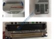
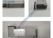
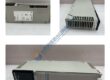
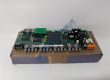
- Model: MVI56-MCM
- Brand: ProSoft Technology
- Series: ControlLogix Platform (1756)
- Core Function: Integrates Modbus serial devices into ControlLogix via the backplane
- Type: Modbus Master/Slave Communication Module
- Key Specs: 2 Serial Ports, RTU/ASCII protocols, 5,000-word Database
- Condition: New Original (New Surplus), not refurbished
Product Introduction
As a peer in the industrial automation space, I view the ProSoft MVI56-MCM as the “workhorse” for serial integration in ControlLogix environments. While Ethernet-based protocols are the modern standard, thousands of field devices—from legacy power meters to VFDs and specialized sensors—still rely on Modbus RTU. This module provides a direct, high-speed backplane interface that eliminates the need for external gateways.
What makes the MVI56-MCM particularly effective is its independence from the ControlLogix processor’s scan cycle for protocol timing. It handles the Modbus “handshaking” and CRC checking internally, merely presenting the final data to the PLC tags. This architecture ensures that even with two ports running at 115.2 kbps, your processor overhead remains minimal.
Key Selling Points & Differentiators
- Dual-Port Independence: Configure Port 1 as a Master to poll field instruments while Port 2 acts as a Slave to provide data to a third-party SCADA system.
- Jumper-Selectable Physical Layer: Supports RS-232 for short distances, or RS-422/485 for multi-drop daisy chains up to 4,000 feet without extra converters.
- Verified Functional Load Test: We subject every module to a 24-hour communication cycle on a 1756-A7 test bench to ensure no “dropped packets” or thermal drift occurs under load.
- Not Recommended For: High-speed motion or safety-critical interlocking where sub-20 ms response is required (serial latency is typically >50 ms depending on baud rate).
- Compliance: Built to meet UL/cUL Class 1, Division 2 standards for use in hazardous locations.
Quality Transparency Strategy
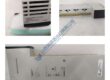
- Incoming Inspection: We verify the revision level of the PCB and inspect the backplane pins for alignment. Serial numbers are tracked to ensure hardware authenticity.
- Live Functional Test: The module is powered in a ControlLogix rack. We use a Modbus simulator to perform “Write” and “Read” commands across both Port 1 and Port 2.
- Electrical Parameter Tests: We measure the current draw on the 5.1 V rail. If the draw exceeds 800 mA, the unit is rejected due to potential internal component stress.
- Firmware Verification: The specific firmware (e.g., v2.02) is recorded. We ensure the internal lithium battery is at a nominal 3 V to maintain the internal database during power loss.
- Final QC + Packaging: Units are placed in ESD-shielded packaging with a “QC Passed” label including the date and the technician’s initials.
“Old-Hand” Technical Pitfall Guide
- Firmware & AOI Mismatch:
- Symptom: The module is “Running” in I/O but data registers never update in the controller tags.
- The Fix: The Add-On Instruction (AOI) version in your Studio 5000 project MUST match the module’s major firmware version. Check your firmware via the Config port before importing your AOI.
- The “Jumper” Trap:
- ❗ Warning: If you wire for RS-485 but leave the hardware jumpers in the default RS-232 position, you may blow the serial transceiver chip.
- The Fix: Always pull the module and check the physical jumpers on the side of the board. Don’t assume the previous installer (or the factory) set them for your specific wiring.
- Power Budget Realities:
- Case: Adding an MVI56-MCM to a rack that already has multiple EN2T and Analog cards often pushes a 1756-PA72 power supply to its limit.
- The Fix: This module pulls nearly 1 Amp on the 5 V rail. Always run a power budget check in ProposalWorks before adding this to a populated rack.
- Termination and Grounding:
- Symptom: Intermittent “CRC Errors” or “Timeout” errors on long RS-485 runs.
- The Fix: Ensure a 120-ohm resistor is at both ends of the run. Ground the shield at the ControlLogix rack only to prevent ground loops that confuse the serial signal.
- ESD Handling:
- Case: A tech handled a module by the components rather than the plastic housing during a low-humidity shift; the module worked for two days and then “died” with a solid Red LED.
- The Fix: Always use an ESD strap. These serial transceivers are particularly sensitive to static discharge at the port pins.

500A AC DC WIRING CONNECTOR BOND LOSS DETECTION TESTER
0-500A DC VAPOR DEPOSITION CRUCIBLE HEATER TEMPERATURE
500 AMPS BOAT ELECTRONIC SYSTEM TESTER BATTERY CHARGER
500A 10KW CAR AUDIO POWER AMPLIFIER 12VDC POWER SUPPLY
O-20VDC 500A BOAT MARINE RADAR ELECTRICAL SYSTEM TESTER
500A DESTRUCTIVE ELECTRONIC COMPONENT CONNECTOR TESTER
10000 WATT CAR AUDIO POWER AMPLIFIER 12VDC POWER SUPPLY
0-10,000 WATT PIPE TUBING HEATER POLYMERIZATION CONTROL
LAMBDA EMS 40-250-2-D 0-40V@ 0-250A DC LAB POWER SUPPLY
LAMBDA EMS 20-250-2-D O-20V@ 250A DC BENCH POWER SUPPLY
LAMBDA 0-40V@ 0-250A 10KW REGULATED DC LAB POWER SUPPLY
0-250AMP DC CIRCUIT BREAKER CONNECTOR RESISTANCE TESTER
O-20V 250A AIRCRAFT ELECTRICAL AVIONICS DC POWER SUPPLY
0-20V 250A STARTER MOTOR ENGINE TESTER DC POWER SUPPLY
O-20VDC 250A BOAT ELECTRICAL SYSTEM TESTER POWER SUPPLY
250A AC POWER LINE WIRING GROUND BOND BONDING TESTER
250A 5000W CAR AUDIO POWER AMPLIFIER 12VDC POWER SUPPLY
250AMP ELECTRIC ELECTRONIC DESTRUCTIVE COMPONENT TESTER
LAMBDA 0-40V@ 0-250A 10KW REGULATED DC LAB POWER SUPPLY
POWER TEN P63C-30200 0-30V@0-220A VARIABLE DC SUPPLY
US 0-30V@ 0-220A 6KW DIGITAL REGULATED DC POWER SUPPLY