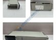
Product Core Brief
- Model: N3000-IMC
- Brand: NORIS MARINE
- Series: N3000
- Core Function: Intelligent monitoring controller designed for marine and industrial automation applications.
- Type: Industrial Monitoring Controller
- Key Specs:
- Input Voltage: 24 V DC
- Communication: Modbus RTU, Ethernet
- Power Consumption: 15 W
Product Introduction
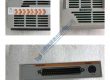
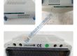
The NORIS MARINE N3000-IMC is an advanced industrial monitoring controller specifically designed for marine and industrial automation systems. It serves as the central hub for monitoring various parameters within a control system, ensuring that equipment operates optimally and within safety limits. Equipped with Modbus RTU and Ethernet communication protocols, the N3000-IMC can easily integrate with existing control systems and provide seamless data exchange.
This intelligent controller is engineered to withstand the rigorous demands of marine environments, where reliability and performance are critical. Its robust design ensures continuous monitoring of machinery, sensors, and system parameters, improving operational efficiency and reducing downtime in complex industrial and marine setups.
Installation & Configuration Guide
Phase 1 — Pre-Installation (est. 10 min)
- Safety: Ensure power is disconnected and wait 5 minutes for residual charge to dissipate.
- Tools: Anti-static wrist strap, multimeter, flathead screwdriver, cable stripper.
- Backup: Document communication settings, I/O configuration, and system parameters.
Phase 2 — Removal (est. 5 min)
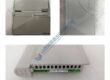
- Label all wiring connections before disconnecting.
- Release the controller from the DIN rail and remove it from the system.
- Inspect connectors for any signs of wear or damage.
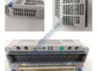
Phase 3 — Installation (est. 10 min)
- ESD Precautions: Wear an anti-static wrist strap.
- Verify the model number matches the N3000-IMC.
- Mount the controller securely on the DIN rail, ensuring proper seating.
- Reconnect wiring according to the saved configuration (tighten to 0.5 N·m torque).
Phase 4 — Power-On & Testing (est. 15 min)
- Verify Voltage: Ensure the input voltage is 24 V DC ±10%.
- Observe LED indicators:
- Green = Normal operation
- Amber = Warning (check wiring or configuration)
- Red = Fault (check power or communication)
- Use NORIS MARINE software or interface to configure and test the controller.
- Verify the controller’s communication over Modbus RTU or Ethernet.
- Test the controller by running through typical monitoring scenarios and validating data.
Troubleshooting Quick-Reference:
- No Communication → Check Modbus RTU or Ethernet wiring and configuration.
- Red LED (Fault) → Review error codes through the system interface.
- I/O Failure → Confirm wiring and signal levels.

Parker Partek CASY-1271 Sampling Valve Manifold Assy
Brinkmann Lauda MGW RC3S Refrigerated Circulator
Motorola MVME187 MVME 187 VME Module
Motorola MVME162-210 MVME 162-210 VME Board
Sencore CR70 Beam Builder Universal CRT Analyzer Restor
Hoffman A603616LP Wall-Mount Type 12/13 Encl. BRAND NEW
Arthur H Thomas Kjeldahl Digestion Rack Model 25
Sound-Craft Lecternette L56B Portable Address System
Acromag 9210 AVME9210 W6D 12-bit D/A Analog Voltage Out
Kinetic Systems 1211-02-11 Vibraplane Isolation Table
Honeywell DCP 700 Series Digital Control Programmer
Tyco Electronics Raychem Cheminax 50 ohm 26 AWG 1K ft.
National Inst. GPIB-1014D VME Controller Card Mainframe
UVP TM-15 Chromato-Vue Dual-Intensity Transilluminator
Motorola MVME374-1 MVME 374-1 VME Module