Description
Technical Architecture & Functional Positioning
(Approx. 400–500 words)
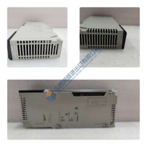
The HCS02.1E-W0070-A-03-NNNN is part of the second-generation Rexroth IndraDrive family, positioned at the motion-control execution layer within an automation system. It interfaces directly with servo motors and field I/O while receiving speed, torque, or position commands from a higher-level motion controller. This drive unit is designed as a compact, panel-mounted module with an integrated power stage, communication interface, and high-resolution encoder processing, enabling precise and reliable control of synchronous and asynchronous servo motors.
From an architectural perspective, the drive employs a high-speed digital signal processor for torque control loops operating at sub-millisecond cycle times. This architecture minimizes velocity ripple and ensures high dynamic response suitable for CNC machining, robotics, precision assembly, and electronic manufacturing. The internal control loops (current, speed, and position) feature advanced feed-forward algorithms and adaptive gain regulation, improving stability even under rapid load changes.
A critical design aspect is its galvanically-isolated control electronics, which reduce electrical noise propagation and protect upstream controllers from ground faults and back-EMF events. The drive also integrates a multi-stage protection system—overcurrent, overtemperature, DC-bus overvoltage, encoder error detection, and STO (Safe Torque Off) safety function—ensuring operational resilience in demanding industrial environments.
On the engineering side, the module’s compatibility with multiple feedback standards such as Hiperface and EnDat allows seamless integration into existing Rexroth installations or cross-vendor retrofits. The drive’s wide input voltage window (380–480 VAC) and compact footprint make it suitable for cabinet retrofits without major power-system redesign.
The design solves several typical engineering challenges. Its fast current loop enhances positioning accuracy, particularly in applications requiring tight tolerance control, while its integrated diagnostics reduce commissioning time and simplify troubleshooting. For OEMs, the ability to support multiple motor families via software configuration lowers lifecycle cost and eliminates the need for multiple drive models across projects.
Typical Application Scenarios
- Used in robotic arm drives for coordinated multi-axis motion with high dynamic response
- Applied in CNC milling/lathe machines for precision spindle and feed-axis control
- Utilized in packaging lines where rapid acceleration and deceleration cycles demand stable torque control
- Integrated into electronics assembly and SMT equipment for micro-positioning
- Serves as a drop-in replacement in legacy IndraDrive-based automation systems, supporting retrofit and performance upgrades
- Suitable for automated storage and retrieval systems (AS/RS) requiring steady load handling and low noise
Quality Standards & Testing Procedures
(Approx. 400–500 words)
In industrial automation environments, unverified drive modules pose substantial operational risk. The HCS02.1E-W0070-A-03-NNNN undergoes rigorous evaluation to ensure electrical integrity, communication reliability, and long-term stability. Each unit is processed through a standardized and repeatable SOP designed for servo drive applications.
Visual Inspection & Cleaning
Every unit is inspected for PCB discoloration, cracked solder joints, capacitor swelling, previous repair traces, or connector wear. The module is cleaned using ESD-safe solvents to remove dust, flux residues, and airborne contaminants that could affect thermal performance.
Live Testing
The drive is powered continuously for ≥24 hours on a genuine IndraDrive test rack. During this test, technicians monitor DC-bus voltage, IGBT temperature, output current stability, fan operation, and noise levels. Any deviation from expected tolerances triggers further diagnostic analysis.
Functional Verification
- Motor Control Test: The drive operates paired motors through full torque, speed, and position loops under varying loads.
- Encoder Interface Check: Multiple encoder types (Hiperface, EnDat) are simulated to validate feedback processing.
- Regeneration & DC-bus Load Test: Verifies handling of dynamic braking energy and bus-voltage stability.
- Communication Diagnostics: Ensures error-free operation under SERCOS III or configured fieldbus protocols.
Firmware Verification
Firmware version and drive parameter sets are logged, ensuring compatibility with target controllers. When the unit contains firmware variants mismatched with customer requirements, recommendations are provided proactively.

ZEISS EPIPLAN APOCHROMAT 150X/1.25W DIC OBJECTIVE
Polaroid DMC 1 Digital Microscope Camera
HP 85131D 85131-60009 85131-60010 Cable Set
Agilent QUAD APG E7088 66534 4426 BOARD
ZHONE MALC-G SHDSL-24
OPHIR NOVA DISPLAY POWER METER + SENSOR 150C-Y-3/12 YAG
Rofin leistungsmessung Laser
FORCE SPARC CPU-8VT CPU-8VT/64-170-2 VME MAINFRAME CPU
GSI lumonics 6056049 P/N:6056049 Board
Agilent 5086-7471 TBR Step Generator
Vision Engineering Oblique and Direct Viewer 360° Lynx
Matrox Corona 2 Frame Grabber Y7030_02 Rev. A Corona II
RVSI 63552 REV-A VME SLAVE PROCESSOR with TTM610-E
RVSI 53003 VME MASTER BOARD REV-B
RVSI 63551 X63551 VME MASTER BOARD REV-B
RVSI 63552 REV-B VME SLAVE PROCESSOR with TTM610-E – 11
Allen Bradley SLC 500 1747-L532 5/03 CPU 13 Slot Rack
FUJI 4800 VME-48108-00F-G Vision Processing Board
Agilent 5087-7020 Coupler with Bias Tee 50 OHM