Description
Technical Architecture & Functional Positioning
(≈450 words)
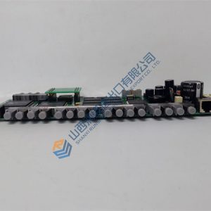
Within the IndraDrive architecture, the HCS03.1E-W0210-A-05-NNBV functions as the primary power stage responsible for converting incoming AC supply into a controlled DC bus and subsequently generating the precise PWM output required for servo motor regulation. It resides at the drive power layer, directly interacting with high-performance motor feedback loops executed by the associated control section (e.g., a CSB/CSH control card).
The engineering design of this module reflects Rexroth’s standard approach for industrial high-capacity drives: an insulated-gate bipolar transistor (IGBT) power bridge, high-precision DC bus monitoring circuits, and galvanically isolated command interfaces. The IGBT-based inverter stage ensures fast current rise time and minimal switching losses—critical for dynamic servo applications such as metal forming, high-speed CNC machining, and robotics. Integrated current and temperature sensors feed real-time data to the control electronics, enabling cycle-accurate torque control and active protection against overload, short-circuit, and thermal runaway.
A notable architectural feature is its robust DC bus energy management. By supporting external braking resistors through a dedicated chopper circuit, the drive reliably dissipates regenerative energy from rapid deceleration events. This is essential in applications with frequent fast stops, heavy table dynamics, or high-inertia motors, preventing DC bus overvoltage and maintaining uninterrupted system operation.
The module’s internal diagnostics architecture continuously supervises IGBT module temperature, fan performance, bus voltage balance, and grounding integrity. Any irregularity triggers fault isolation routines, designed to protect upstream supply networks and reduce risk of cascading failures in multi-axis drive cabinets. Such design choices align with industry demands for predictable failure behavior and simplified troubleshooting.
In engineering practice, this drive’s value becomes particularly evident in demanding installations. Its high continuous output current (210 A) allows deployment in large-frame servo motors and heavy-duty asynchronous motors, supporting cranes, press automation, rolling mills, and other dynamic load systems. Meanwhile, the standardized mechanical form factor and front-accessible terminals streamline retrofits, where installation space and wiring continuity are critical constraints.
Typical Application Scenarios
- Applied in metal processing lines for high-power roller drive control under rapidly changing torque loads
- Used in CNC machining centers for spindle or heavy-axis servo control where high continuous current is required
- Integrated into industrial robotics and multi-axis automation where large inertia demands precise dynamic control
- Serves as a compatible replacement for earlier Indramat drive modules in modernization projects
- Deployed in offshore equipment, press automation, and high-duty-cycle machinery requiring robust thermal performance
Quality Standards & Testing Procedures
(≈450 words)
In heavy-industrial automation, a high-power drive module that has not been properly verified can trigger catastrophic equipment stoppages, electrical faults, or thermal failures. Recognizing this risk, each HCS03.1E-W0210-A-05-NNBV undergoes a stringent test and inspection protocol built to replicate real operational environments. Our quality philosophy centers on reliability, traceability, and ensuring that every drive operates within original Rexroth parameters.
The evaluation process begins with a comprehensive visual inspection. Technicians review solder joints, IGBT module integrity, connector pins, fan assemblies, and capacitor conditions to identify early indicators of stress or unauthorized repair. Any contamination—oil, dust, residue—is removed using ESD-safe solvents to prevent insulation breakdown or thermal inefficiency during operation.
Live testing constitutes the core of the verification process. Each unit is powered on a genuine IndraDrive test bench for a minimum of 24 hours. During this period, critical metrics such as bus voltage, current stability, thermal growth, and cooling airflow are continuously monitored. Load simulation devices emulate real motor current patterns to validate switching behavior and overload management.
Functional verification covers multiple dimensions:
- Output waveform analysis ensures the IGBT bridge produces stable PWM signals under all tested frequencies
- Servo control loop communication is tested through SERCOS or the drive’s configured interface, confirming deterministic communication without packet loss
- The braking chopper circuit is evaluated using controlled regeneration pulses to confirm safe energy dissipation
- Protection mechanisms—short circuit response, overtemperature threshold, under-voltage lockout—are individually triggered and logged
Firmware and configuration data are recorded to ensure compatibility with user systems. If version discrepancies exist between customer requirements and device configuration, technicians notify customers prior to shipment to avoid integration issues.
Finally, each drive receives a serialized Quality Test Report that includes measured values, ambient conditions, diagnostics logs, and technician approval signatures. Only units meeting all performance thresholds proceed to inventory.

OMRON C200PC-ISA12-1 + C200PC-CN221 + ES100-CT023-202
GE Fanuc TOTAL CONTROL GQPI31200E2P 9″ QUICKPANEL TS
HILBERLING HG-111 RF-GENERATOR ROFIN SINAR QS-DRIVER
Rofin Sinar 131100088 DILAS Diodenlaser Gmbh 780-1000nm
Mitsubishi Melsec AJ72 P25 AX41 AY51 AY13 Full PLC
MPCMM0002Q Command Management Module
Kollmorgen Servostar 600 610 S61000-SE
FUJI 4800 VME-48316-32F Rev C Vision Processing Board
FUJI 4800 VME-48316-32F Rev F Vision Processing Board
TOTAL CONTROL QPH2D100L2P HANDHELD OPERATOR INTERFACE
Agilent 5023-1209 5067-1335 Board
COGNEX VPM-8120X-5060 VM28A 801-8130-01K FRAME GRABBER
Teknic SST-3000-829 Servo Drive M-5075-829 SERVO Motor
Agilent 34970A Data Acquisition / Switch Unit Opt 001
GALIL DMC-1770 7AXIS MOTION CONTROLLER + CB 50-100 CARD
Vision Engineering Image Capture + Camera
QUANTRONIX QS27-4S-B-QX1 LASER Q SWITCH
Agilent 33321-60061 Attenuator, 65dB DC Block
QUANTRONIX QS27-4S-B-QX1 LASER Q SWITCH
Whedco DSP Motion Control IMJ-313E-X-D MTR-3N31 Motor
MITSUBISHI F943GOT-SBD-DHI GRAPHIC OPERATIONS TERMINAL
HP/Agilent E4440-60456 Assembly electronic attenuator
Omron NT600S-ST121-V1 Interactive Display 9″ touch scr
LEICA S4E STEREO MICROSCOPE HEADV