
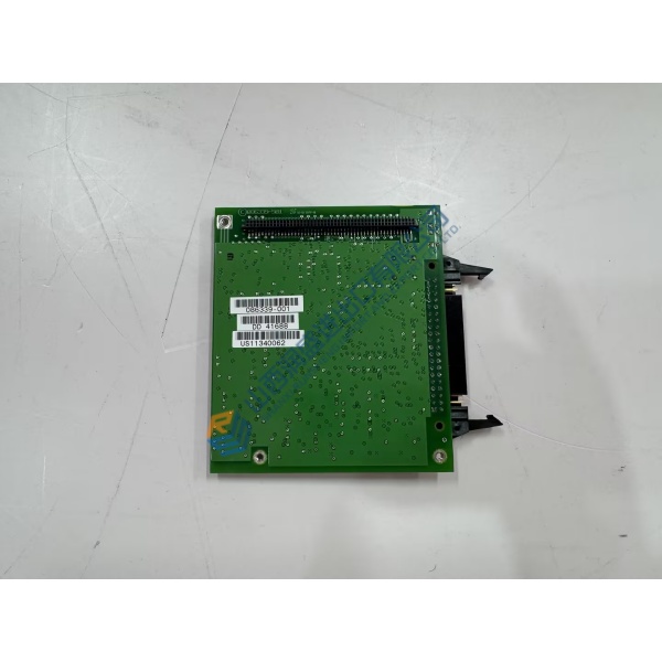
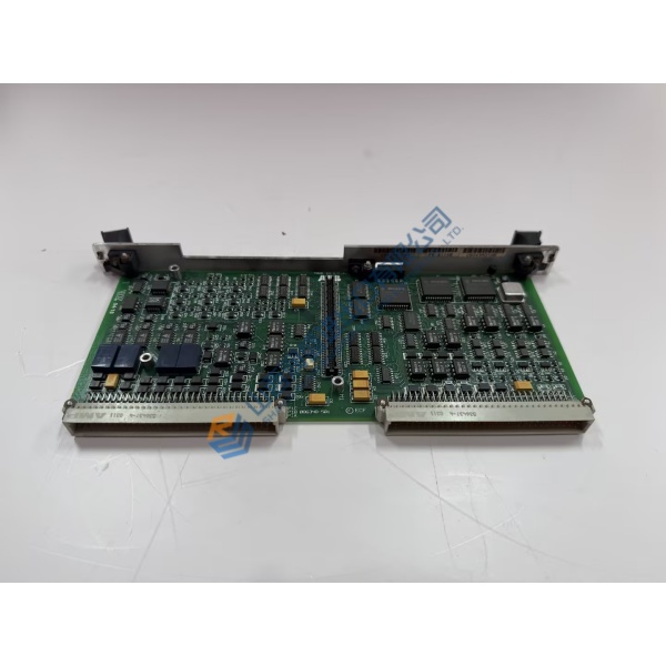
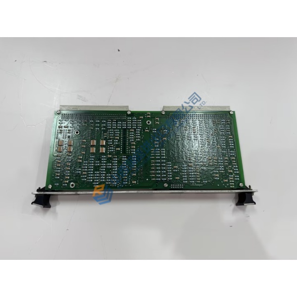
Description
Product Introduction
Running heavy gas turbines on outdated hardware often triggers spurious trips during load transitions. The 354A1513P032 GE servo valve driver board solves this stability bottleneck by delivering precise current regulation to liquid fuel and inlet guide vane (IGV) actuators. Designed for GE SPEEDTRONIC Mark VI turbine control architectures, this module translates high-level digital positioning commands into smooth analog current loops, maintaining valve drift within a tight ±0.2% tolerance under severe thermal conditions.
Field deployments across industrial power plants prove that proper driver calibration keeps actuation response times well under 15 ms. Replacing a degraded driver card restores tight loop control on fuel splitters and bypass dampers immediately. Honestly, running worn analog boards on critical gas units is a gamble nobody needs to take during peak summer dispatch. This unit ships pre-tested from surplus stock, minimizing unplanned outage hours when your primary control rack signals a servo loop fault.
Key Technical Specifications
- Parameter: Value
- Part Number: 354A1513P032
- Manufacturer: General Electric
- System Architecture: SPEEDTRONIC Mark VI
- Module Function: Servo Valve Driver Circuit Board
- Input Voltage: 24 V DC (±10% operational margin)
- Output Signal Channels: Dual/Triple redundant servo loop outputs
- Current Driver Range: 0 to ±100 mA (configurable for standard Moog/Abex valves)
- Operating Temperature: −30 to +65 °C (−22 to +149 °F)
- Backplane Interface: Mark VI Control Rack VME-style edge connection
- Position Feedback Inputs: LVDT / RVDT feedback signal processing
- Isolation Rating: 1,500 V RMS functional field-to-logic isolation
Installation & Configuration Guide
Phase 1 — Pre-Installation (est. 10 min) De-energize the Mark VI rack power distribution unit completely. Wait 5 minutes to let rack filter capacitors discharge. Gather a T15 Torx driver, ESD wrist strap, and a digital multimeter. Export current turbine control constants from the CIMPLICITY / Toolbox software workstation. Photograph existing wiring on the terminal block and document every DIP switch configuration on the card you plan to pull.
Phase 2 — Removal (est. 5 min) Label all connected field cables on the terminal headers. Loosen the upper and lower retaining screws on the card faceplate. Disengage the card ejector levers simultaneously, pulling the module straight out perpendicular to the backplane to avoid bending bus pins. Inspect the backplane slot for debris or bent pins before inserting replacement hardware.
Phase 3 — Installation (est. 10 min) Attach your ESD wrist strap to a verified frame ground point. Verify the replacement 354A1513P032 part number on the PCB silkscreen. Replicate jumper configurations and switch positions from your reference photos. Align the board edges with the chassis card guides, slide it inward smoothly, and press firmly until the ejector handles latch shut. Torque faceplate screws to 0.5 N·m and reconnect terminal plugs.
Phase 4 — Power-On & Testing (est. 15 min) Apply 24 V DC power to the rack. Observe the diagnostic LEDs during initialization: green power rail indicators must stay solid, while fault red LEDs should turn off after POST completes. Launch GE Toolbox software to establish a communication handshake with the rack controller. Download card configuration files, calibrate LVDT zero and span settings, and cycle the servo valve through one complete 0–100% stroke test. Log the replacement event in your site maintenance software after confirming 30 minutes of stable operation.
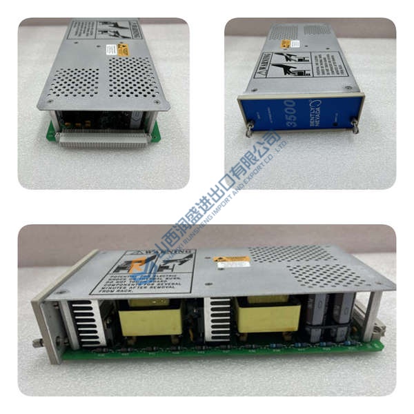
Troubleshooting Quick-Reference
- No Comm / Card Not Detected: Verify card seating in the VME slot. Inspect backplane connector pins for physical damage. Check rack power supply 24 V rail output.
- SERVO FAULT Red LED Active: Firmware mismatch or uncalibrated LVDT loop. Check coil resistance with a Fluke 115 multimeter (typical 80–1,000 Ω depending on valve model).
- Valve Oscillations / Instability: Verify shield grounding on feedback wiring. Check DIP switch current loop gain settings against original OEM records.
Quality Transparency
Incoming Inspection: We verify source traceability against original OEM packing documentation and customs manifests. Anti-counterfeit checks include verifying PCB serial numbers, board layout silkscreens, and security labels. Technicians conduct physical inspections under high magnification to check for solder fatigue, track repair marks, board yellowing, or edge connector corrosion. Accessories and terminal blocks are verified against factory bill-of-materials.
Live Functional Test: Cards undergo a bench-top power-on self-check where LED power-up sequencing is logged. We connect the board to a simulated Mark VI rack backplane to test communication handshakes over the control bus. Using calibrated signal generators, our team performs full I/O signal simulation across all servo driver outputs and LVDT inputs. The board runs under 80% maximum rated load for over 24 hours inside a thermal chamber, with temperature rise logged to ensure thermal stability — outputting a formal Test Report upon completion.
Electrical Tests: Insulation resistance testing is performed with a 500 V megohmmeter between field terminal pins and logic ground, requiring >10 MΩ to pass. Ground continuity tests confirm low-resistance frame paths. Dielectric withstand testing verifies barrier integrity across isolated channels.
Firmware Verification: The installed firmware and FPGA logic versions are read via diagnostic tools and recorded in our system database. Physical jumper blocks and DIP switch factory settings are photographed before sealing.
Final QC & Packaging: A senior technician reviews test logs and signs off on the release form. The 354A1513P032 module is sealed inside a heavy-duty anti-static ESD bag, wrapped in high-density foam, and packed into a corrugated export box. A QC Passed sticker bearing the inspection date and technician ID seals the final outer packaging. Test photos and video records are available on request. All units are confirmed functional after completing tests above.



