Description
Product Introduction
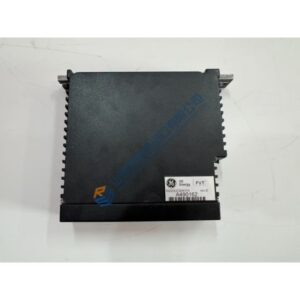
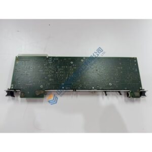
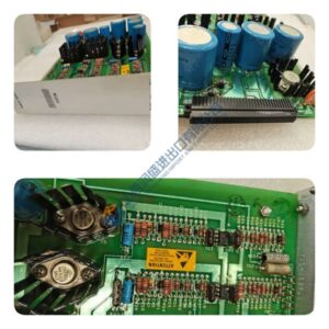
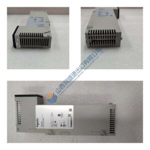
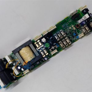
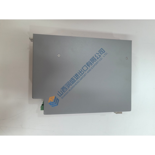
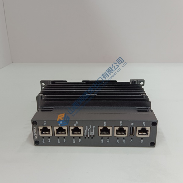
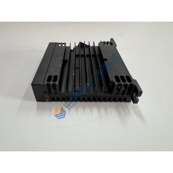
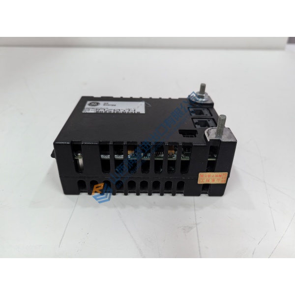
The WOODWARD 9907-135 is a GS3/LQ driver module for turbine fuel valve control. It takes a 4–20 mA command signal from the governor and drives the actuator to position liquid or gaseous fuel valves.
Field deployments on LM-series gas turbines show this module handles the current loop directly — no separate amplifier needed. The 24 A output capacity drives GS3 and LQ25 actuators without an intermediate stage. Response time lands under 2 ms, which keeps fuel metering tight during load swings .
Installation & Configuration Guide
Phase 1 — Pre-Installation (est. 10 min)
De-energize the control cabinet and verify zero voltage at the module terminals with a Fluke 115 multimeter. Photograph all wiring connections and terminal positions. Record the 4–20 mA signal source routing and feedback resolver wiring. ❗ Do not reverse power polarity — the module has no reverse-polarity protection .
Phase 2 — Removal (est. 5 min)
Label every wire: power, 4–20 mA demand signal, actuator output, and resolver feedback. Release mounting screws and pull the module from the panel. Inspect terminal blocks for corrosion or heat damage.
Phase 3 — Installation (est. 10 min)
ESD wrist strap on, grounded to cabinet. Verify the replacement is 9907-135. Mount the module and secure screws. Reconnect wiring per photos. Use shielded twisted-pair cable for the 4–20 mA signal — terminate shield at cabinet ground only . Verify actuator feedback wiring polarity before power-up.
Phase 4 — Power-On & Testing (est. 15 min)
Apply 24 VDC supply. Verify STATUS LED behavior. Inject a 12 mA signal (50% demand) and observe actuator movement. Check feedback resolver tracking. Run a step response from 4 to 20 mA and confirm actuator reaches full position within specified response time. Log the swap with date and turbine serial number.
Troubleshooting Quick-Reference:
- No actuator movement → check 24 VDC supply, 4–20 mA signal presence, actuator coil continuity
- Erratic positioning → verify resolver feedback wiring and shield grounding
- ❗ Overcurrent trip → actuator coil short or excessive mechanical load; measure coil resistance
- Communication fault → check RS-485 wiring if remote monitoring used