
Description
Product Introduction
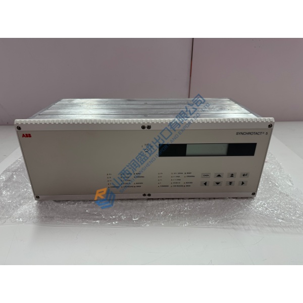
ABB AO2040 forms the wall-mounted central housing for the Advance Optima AO2000 continuous gas analyzer family. It accepts one or more analyzer modules (Uras26, Magnos, Caldos, Fidas24 and others) plus the electronics module, power supply and optional pneumatics, delivering simultaneous multi-component measurement in process and emissions applications.
Field experience with AO2000 installations shows the wall-mount format cuts cabinet space versus the 19-inch AO2020 rack version while still allowing system-bus extension up to 350 m for remote modules. Power draw stays under 187 VA at 100–240 V AC; the stainless-steel enclosure reaches IP54 with the connection box fitted.
Installation & Configuration Guide
Phase 1 — Pre-Installation (est. 10 min)
De-energize the supply and wait at least 5 min for residual discharge. Gather tools: torque screwdriver, multimeter (Fluke 115 or equivalent), ESD wrist strap and mat. Export any existing configuration if replacing a unit. Photograph the existing wiring layout, terminal labels and any DIP/jumper settings on the electronics module.
Phase 2 — Removal (est. 5 min)
Label every wire before disconnection. Release the wall-mount fasteners (M8 or M10). Pull the housing straight away from the wall; inspect the mounting surface and any residual gas-line fittings.
Phase 3 — Installation (est. 10 min)
Apply ESD protection first. Verify the part number on the nameplate matches the ordered AO2040 configuration. Mount with four M8/M10 screws; leave clearance on the left side for door swing (~60 mm) and above for top-access modules (~300 mm). Replicate any prior I/O module arrangement and terminate wiring at ~0.5 N·m. Complete the pre-power checklist: polarity, ground continuity, gas-path integrity.
Phase 4 — Power-On & Testing (est. 15 min)
Confirm supply voltage is within 100–240 V AC ±10 %. Observe LEDs (green = RUN, red flash = ERR, amber flash = DIAG). Connect the programming interface, download the application, and run a full functional test of measured values, digital outputs and one complete calibration cycle. Confirm stable operation for >30 min, then log the swap in the maintenance record.
Troubleshooting quick-reference:
- No comms → check Ethernet/IP settings, cable and switch port
- ERR steady → firmware or module mismatch; verify versions
- Download fails → confirm cable type and software revision



