
Description
Product Introduction
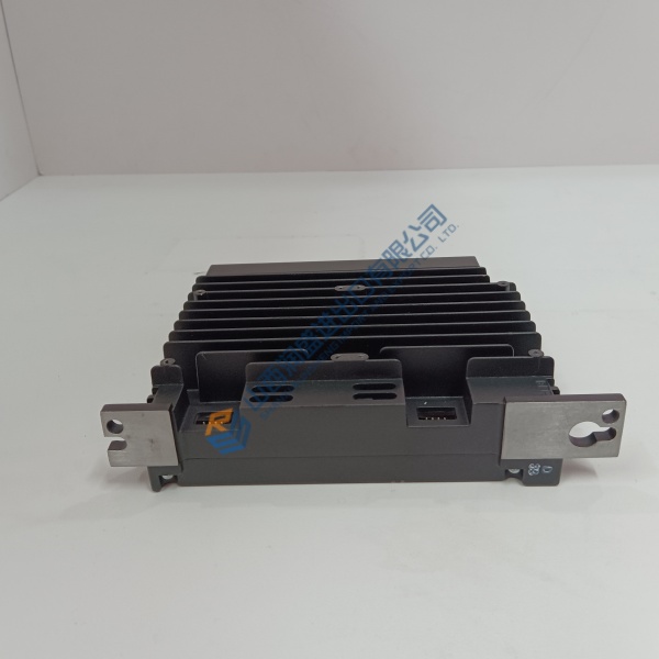
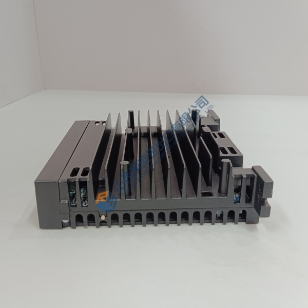
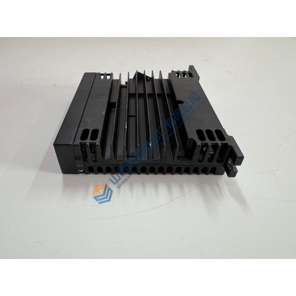
Legacy distributed control systems often experience total sub-rack outages when central processing units suffer thermal degradation or bus communication failures. The ABB CMA120 processing module eliminates these plant downtime risks by providing dependable logic execution across legacy MasterPiece and Advant architectures.
Designed to fit directly into standard ABB sub-rack card cages, this module maintains accurate signal conditioning and steady data transfer across industrial control loops. In my experience, dropping in this module as a direct replacement restores system communication and prevents costly process interruptions on critical production lines.
Installation & Configuration Guide
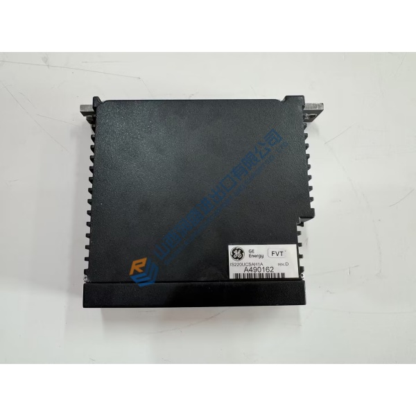
Phase 1 — Pre-Installation (est. 10 min): Shut off power to the sub-rack enclosure and wait 5 minutes for bus energy to clear. Gather a flat-head screwdriver, antistatic wrist strap, and a digital multimeter. Photograph all jumper setups, DIP switches, and adjacent slot assignments prior to removing the old module.
Phase 2 — Removal (est. 5 min): Loosen the top and bottom retaining screws on the front panel. Carefully pull the card edge release levers to disengage the rear connectors, then slide the unit straight out to avoid bending backplane pins. Inspect the rack guide rails for dust or physical obstruction.
Phase 3 — Installation (est. 10 min): Secure your ESD wrist strap to the panel ground point. Check that the part number on the module matches your engineering drawing. Match all hardware jumpers and DIP switch banks to your original photos. Slide the module evenly into the guide slots until it seats completely into the backplane connector, then tighten retaining screws to 0.5 N·m.
Phase 4 — Power-On & Testing (est. 15 min): Measure 24 V DC supply rails to confirm steady input power. Turn on the sub-rack power switch and observe the front panel LEDs (green RUN LED steady). Connect your engineering software workstation, download system parameters, and test control loop response. Monitor the system for 30 minutes to verify error-free operation.
Troubleshooting Quick-Reference:
- FAULT LED illuminated → Re-check backplane seating and verify jumper settings.
- No power indication → Test 24 V DC backplane supply with a Fluke multimeter.
- Communication error → Inspect backplane connector pins for corrosion or alignment issues.



