
Description
Product Introduction
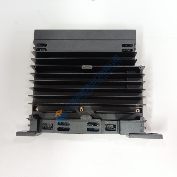
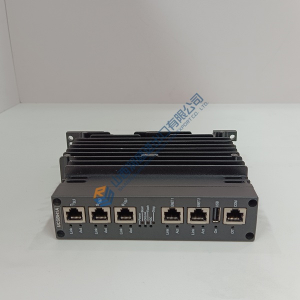
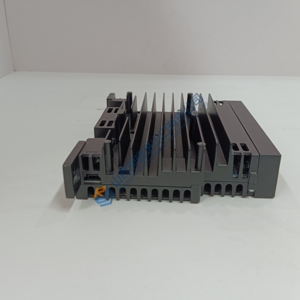
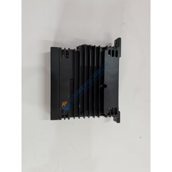
ABB CMA120 (part number 3DDE300400) is a control and signal-processing module used in ABB industrial automation platforms. It handles communication, I/O interfacing or logic execution within Advant OCS, AC 800M or related DCS architectures.
Field experience shows these boards keep process loops running when a spare is needed quickly. Power is drawn from the system backplane or 24 V DC rail; the compact PCB format fits standard ABB module slots or DIN-rail bases. Always verify the exact revision and firmware against the host controller before installation.
Installation & Configuration Guide
Phase 1 — Pre-Installation (est. 10 min)
De-energize the controller rack and wait 5 min for residual discharge. Tools: ESD wrist strap, multimeter (Fluke 115), torque screwdriver. Export current configuration and photograph module position, backplane connectors and any DIP/jumper settings.
Phase 2 — Removal (est. 5 min)
Label every cable and ribbon. Release the module latch or screws. Withdraw the board perpendicular to the backplane; inspect connector pins for bent or corroded contacts.
Phase 3 — Installation (est. 10 min)
Apply ESD protection first. Verify the part number CMA120 / 3DDE300400 matches the ordered unit. Seat the module firmly until the latch clicks. Replicate prior DIP/jumper positions from photos. Reconnect wiring and run the pre-power checklist.
Phase 4 — Power-On & Testing (est. 15 min)
Apply system power and observe status LEDs. Connect engineering tool (Control Builder or equivalent), download configuration if required, and verify communication and I/O points. Run a functional test of the associated control loops for >30 min. Log the module swap.
Troubleshooting quick-reference:
- No communications → check backplane seating, power rail and firmware version
- ERR steady → module or revision mismatch; confirm order code
- Download fails → verify engineering software version and cable



