
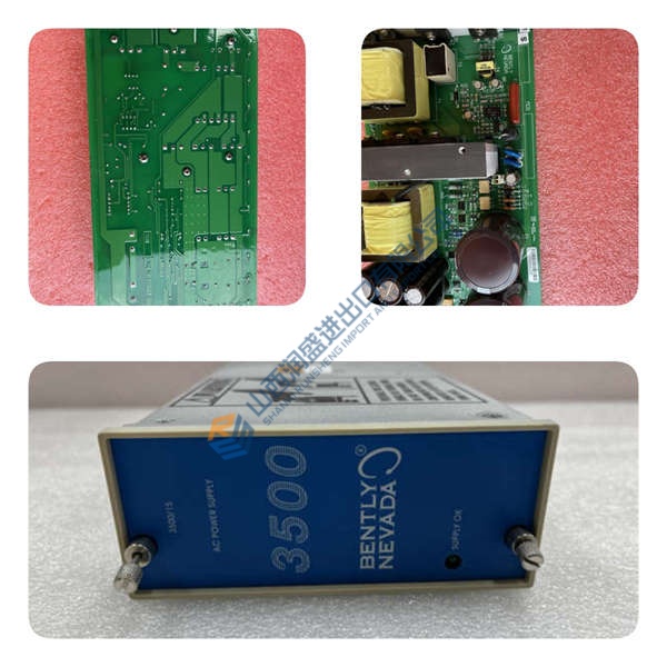
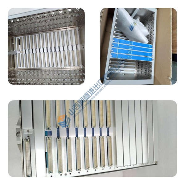
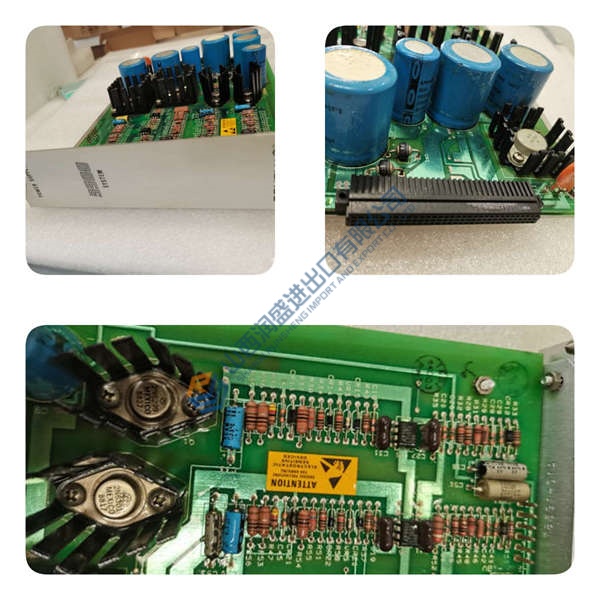
Description
Product Introduction
ABB PVD164A01R1066 serves as a high-density digital output interface within ABB Procontrol P14 power generation control architectures. Delivering 16 galvanically isolated output channels, this module converts internal bus commands into discrete physical signals for solenoid valves, interposing relays, and status indicators. Powered directly via the 24 V DC system backplane, the unit maintains signal integrity in harsh electrical environments common to utility turbine halls. In field deployments of AC800M systems, dependable field driving logic prevents un-sequenced plant trips.
Finding verified spare parts for mature power plant control loops can disrupt outage schedules. Fitting directly into standard Procontrol subracks, the card provides seamless replacement for legacy output cards without necessitating system wiring updates. Is this design choice actually clever? Absolutely, because channel group isolation protects sensitive rack logic from external ground faults and inductive field spikes. Listed pricing serves as reference only; actual market pricing varies according to global stock availability. Contact our sales office today to request an official quote on current inventory.

Quality Inspection and Verification SOP
In our testing facility, every incoming module undergoes meticulous multi-point verification before entering storage. We verify source documentation against OEM shipping manifests and customs paperwork. Technicians perform anti-counterfeit checks, inspecting serial numbers, PCB batch codes, and solder mask uniformity. Physical checks ensure zero backplane pin bending, conformal coating flaking, or card edge oxidation.
Live functional testing begins by inserting the module into a energized Procontrol test rack while monitoring power rails with a Fluke 115 multimeter. Observing startup LED behavior, we initiate communication handshakes across the rack backplane bus. Technicians run full 16-channel signal switching routines against resistive and inductive loads, logging thermal distribution over a continuous 24-hour load test. Insulation resistance is verified using a 500 V megohmmeter to ensure channel-to-ground isolation exceeds 10 MΩ. Firmware revisions are logged, and backplane jumpers are photographed for client archives. Following final technician sign-off, the card is wrapped in anti-static shielding and sealed in padded shipping boxes. Test photos and raw video recordings remain available on request. Units are confirmed functional after completing all tests above.
Technical Pitfall Guide for Integration Engineers
Having supported dozens of power station overhauls, our engineering team highlights five critical mistakes that stall installations.
- Backplane Connector Pin Damage: Forcefully seating the module into a misaligned slot bends delicate backplane connector pins. Inspect subrack guide rails for debris prior to insertion. Slide the card smoothly and seat it with firm, even thumb pressure.
- Inductive Surge Protection Failure: Connecting un-suppressed relay coils directly to output channels causes inductive voltage spikes that destroy output transistors. Install flyback diodes across DC inductive loads at the field terminal block. Photo. Photo. Photo.
- Field Supply Voltage Polarity Errors: Reversing field power polarity on output terminal blocks causes internal freewheel diodes to short the supply rail. Verify wiring schematics with a multimeter before energizing external 24 V DC field loops. Confirm proper shield grounding to prevent signal noise.
- Overloading Output Group Capacity: Exceeding 500 mA per channel or maximum group thermal thresholds leads to channel shutdown. Calculate total loop current and maintain at least 20% power headroom. Add external interposing relays if load currents exceed channel limits.
- Electrostatic Discharge (ESD) Damage: Handling raw circuit boards without grounding accessories risks damaging sensitive CMOS switching transistors — though your mileage may vary depending on ambient humidity. I watched an engineer skip the strap in January. The module smoked on power-up. $2,000 gone. Always wear an ESD wrist strap connected to chassis ground.
Keep these five points in mind and you’ll cut 90% of your rework time.
Installation & Configuration Guide
Phase 1 — Pre-Installation (Estimated Time: 10 minutes)
De-energize main subrack power and disconnect external 24 V DC field supplies. Wait 5 minutes for power supply capacitors to discharge completely. Gather a 3 mm flathead screwdriver, ESD grounding strap, and contact cleaner. Export rack configuration files from the engineering workstation. Photograph original subrack slot positions, wiring harnesses, and backplane jumper configurations.
Phase 2 — Removal (Estimated Time: 5 minutes)
Tag every field terminal block and wire harness before detachment. Unfasten top and bottom module retaining screws on the front panel. Unlatch the ejector levers and pull the module straight out perpendicular to the backplane frame. Inspect the backplane connector slot for dust buildup or bent receptacle pins.
Phase 3 — Installation (Estimated Time: 10 minutes)
Put on a grounded anti-static wrist strap before opening the protective ESD pouch of the ABB PVD164A01R1066. Verify jumper settings match your pre-installation reference photographs. Align the PCB edge with card guides in the designated rack slot and slide the module inward until ejector levers engage. Press firmly until the front plate meets the frame, then tighten top and bottom retaining screws to 0.4 N·m.
Phase 4 — Power-On & Testing (Estimated Time: 15 minutes)
Verify backplane input voltage reads 24 V DC (±10%) using a multimeter before switching on rack breakers. Apply power and observe module status indicators. A steady green RUN LED indicates proper board startup; a red FAULT LED indicates a backplane bus communication failure. Open system engineering software, force all 16 digital output channels high and low sequentially, and verify physical contact closure on field relays. Confirm stable operation for at least 30 minutes before logging the hardware replacement in station maintenance logs.



