
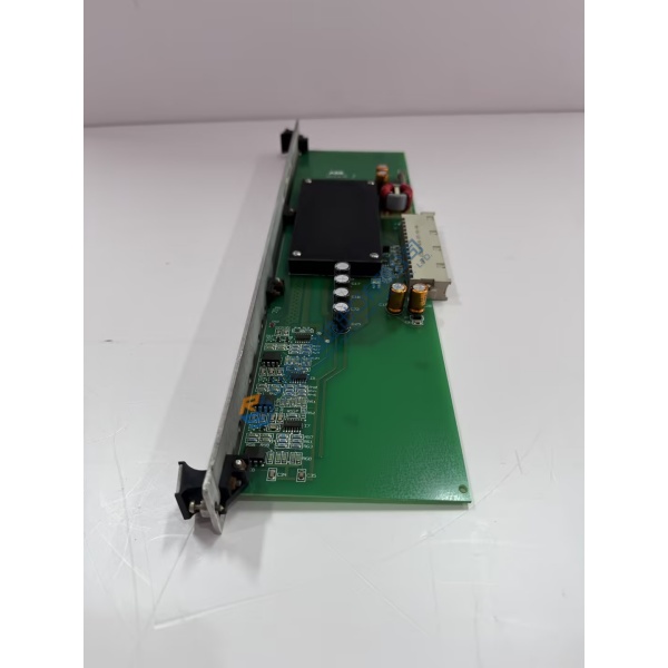
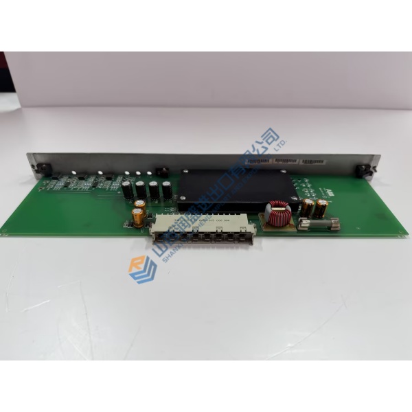
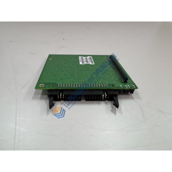
Description
Product Introduction
Robotic cells suffering from intermittent axis drive faults usually point to a degraded drive control card inside the main controller cabinet. The ACU-01B 3HNA024871-001 ABB actuator control unit resolves motor synchronization errors by executing real-time position loop processing and current loop feedback. Designed specifically for ABB IRC5 industrial robot cabinets, this drive unit coordinates multi-axis motion profiling, maintaining spatial arm repeatability within a tight ±0.02 mm margin during high-speed pick-and-place cycles.
Field deployments across automated automotive body shops prove that switching to a calibrated control unit reduces axis servo jitter to under 0.8 ms. Replacing a worn actuator driver card restores smooth motion trajectories and prevents joint torque over-current alarms. Honestly, running aging drive cards in high-duty cycle welding cells is asking for an unexpected robot halt mid-shift. This unit ships fully tested from surplus warehouse stock, allowing plant engineers to clear axis fault codes and resume production without waiting weeks for factory builds.
Key Technical Specifications
- Parameter: Value
- Part Number: 3HNA024871-001
- Model Designation: ACU-01B
- Manufacturer: ABB Robotics
- Control System: IRC5 Robot Controller System
- Module Type: Actuator Control Unit
- Control Voltage: 24 V DC (±10% nominal operating range)
- Axis Drive Channels: Multi-axis synchronous servo control outputs
- Operating Temperature: +5 to +55 °C (+41 to +131 °F)
- Interface Protocol: High-speed ABB internal motion bus
- Mounting Style: Chassis rack panel slot mount
- Enclosure Rating: IP20 industrial cabinet protection level
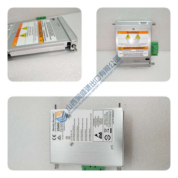
Installation & Configuration Guide
Phase 1 — Pre-Installation (est. 10 min) Turn off the main IRC5 controller safety disconnect switch and lock it out. Wait 5 minutes to allow internal servo drive capacitors to discharge safely. Gather an ESD wrist strap, T20 Torx driver, and a Fluke 115 multimeter. Export the current system diagnostic log and robot system key configuration using RobotStudio software. Take high-resolution photos showing all cable plug positions and hardware jumper settings on the board being replaced.
Phase 2 — Removal (est. 5 min) Label every motor feedback and logic wiring connector plug attached to the module faceplate. Unfasten the module retaining screws at the top and bottom of the unit chassis. Carefully disengage the card from its backplane header, pulling the board straight outward along its side guide rails to avoid putting strain on rear connector pins.
Phase 3 — Installation (est. 10 min) Put on your grounded ESD wrist strap before handling the replacement hardware. Verify the ACU-01B 3HNA024871-001 model code printed on the board silkscreen layer. Set onboard jumper blocks to match your original card photo reference precisely. Slide the unit into its rack slot, push firmly until the backplane connectors fully seat, and torque faceplate screws to 0.5 N·m before reconnecting wire harnesses.
Phase 4 — Power-On & Testing (est. 15 min) Switch on main logic power to the IRC5 cabinet. Check the front diagnostic LEDs: power rail status lights must turn solid green, while red error indicators should extinguish after POST finishes. Connect your PC running RobotStudio to communicate with the controller. Reload axis configuration profiles, perform a slow manual jog test across all robot joints, and execute one full automated motion cycle at 10% speed. Record stable operating metrics after running the cell for 30 minutes.
Troubleshooting Quick-Reference
- Red Error LED / Axis Motion Trip: Check power stage connections. Inspect feedback cables for loose shielding.
- No Communication with Main CPU: Verify module seating on the rack backplane. Inspect connector pins for physical damage.
- Position Drift / Joint Jitter: Re-verify DIP switch gain settings. Measure 24 V DC logic rail supply stability under load.



