Description
Product Introduction
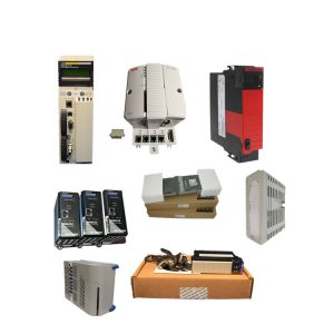
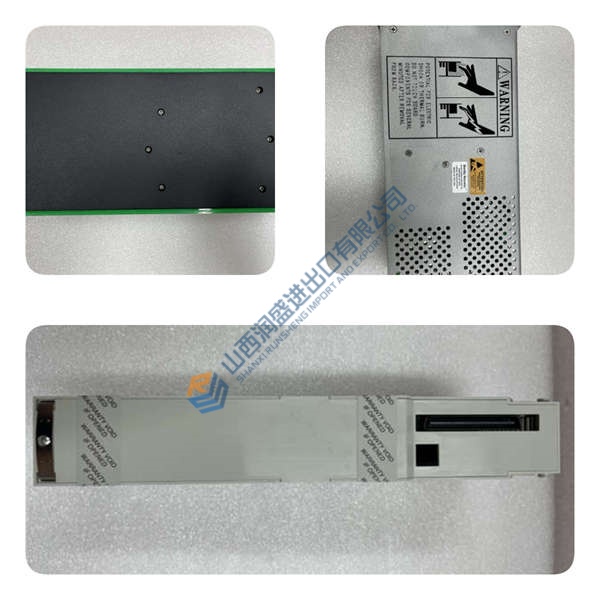
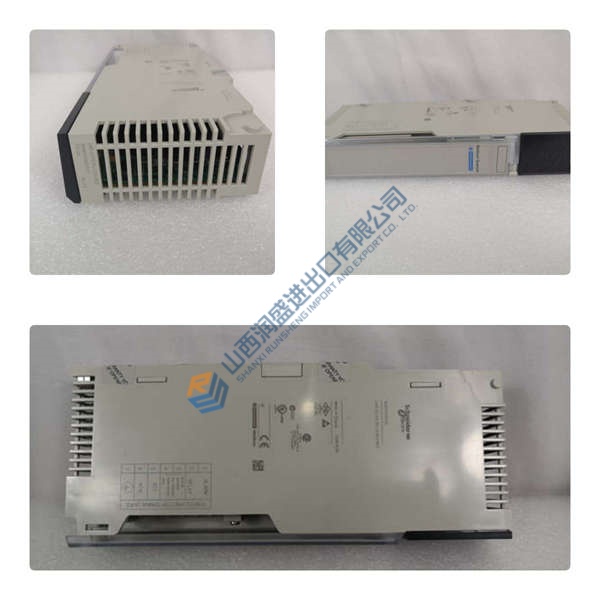
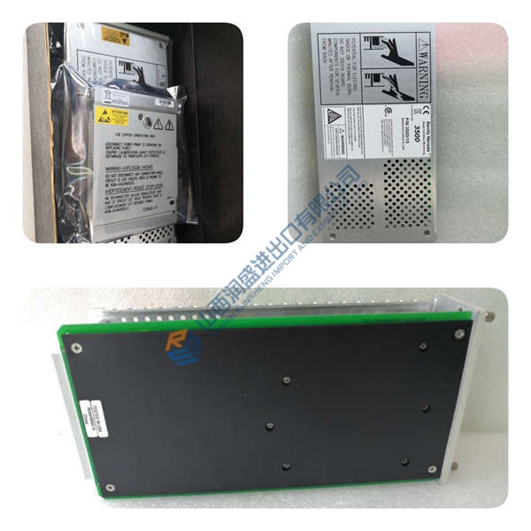
The ALSTOM EP3-E-4-A is a microprocessor-based controller module from the EPIC III family, specifically engineered for electrostatic precipitator (ESP) systems in power plants, cement kilns, and steel mills. It manages high-frequency power supplies that generate the corona field for particulate collection, running advanced spark detection and recovery algorithms to maintain emission compliance.
In field deployments of ESP retrofits, this unit stands out for its dual control modes (automatic/manual) and 10 ms voltage regulation response time. The 4× isolated analog inputs (16-bit, 4–20 mA or 0–10 V) accept transformer current, voltage, and temperature signals, while the thyristor (SCR) phase-shifted output drives the HF transformer directly. If you’re replacing an older EP3-E-4-EN or EP3-E-4-A from a 2010s installation, the EP3-E-4-A is a drop-in swap—same DIN-rail footprint, same terminal layout, same Modbus register map.
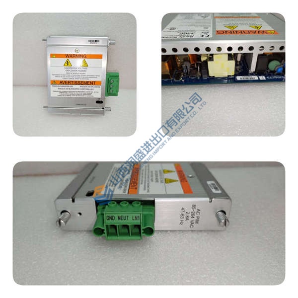
Installation & Configuration Guide
Phase 1—Pre-Installation (est. 10 min)
De-energize the 100–240 V AC supply and wait 5 min for capacitor discharge. Grab a Torx T20, wire strippers, and a Fluke 115 multimeter. Export your current ESP configuration (Modbus register map, spark recovery settings) and photograph the existing module’s terminal wiring, DIP switches, and rack position.
Phase 2—Removal (est. 5 min)
Label every cable before disconnecting—AI1–AI4, AO1–AO2, DI1–DI8, DO1–DO6, Ethernet, RS-485. Release the DIN-rail latch, pull the module straight out perpendicular to the backplane, and inspect the backplane connector pins for bent contacts or corrosion.
Phase 3—Installation (est. 10 min)
Strap on your ESD wristband. Verify the part number matches EP3-E-4-A. Replicate the DIP switch settings from your photos—Modbus address, baud rate, AI range (0–10 V vs. 4–20 mA). Seat the unit until the latch clicks, reconnect the terminal block cables, torque terminal screws to ~0.5 N·m, then run a pre-power checklist: backplane continuity, 100–240 V AC supply polarity, ground bond.
Phase 4—Power-On & Testing (est. 15 min)
Verify supply voltage is 100–240 V AC (±10%). Power up and watch the LEDs: green = RUN, red flash = ERR, amber flash = DIAG. Hook up your HMI or DCS via Ethernet or RS-485, download the ESP configuration, then run a full I/O loop test. Log at least 30 min of stable operation before signing off.