Description
Product Introduction
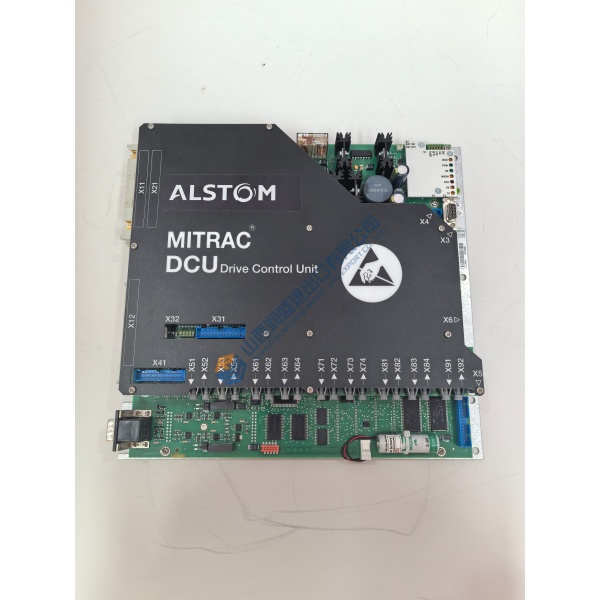
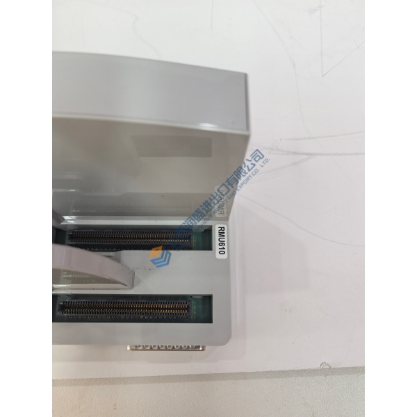
Out on the factory floor, a tripped main drive processor brings an entire rolling line to a dead stop. Identifying a genuine replacement quickly becomes your only priority. The ALSTOM SPU232.2 029.366.817 executes real-time control algorithms and signal management across legacy industrial installations. Grounded in IEC 61131 standards, it fits directly into existing rack architectures without requiring backplane rewiring.
In field deployments of ALSTOM drive controls, this module maintains deterministic signal sampling down to 1.0 ms. The ALSTOM SPU232.2 029.366.817 integrates directly with legacy power electronic interfaces to keep legacy systems running smoothly. Listed prices serve as a baseline reference; actual availability and market pricing fluctuate based on global surplus inventory. Contact our procurement team directly to request an exact quote and confirm current lead times.
Installation & Configuration Guide
Phase 1 — Pre-Installation (est. 10 min)
De-energize the entire cabinet power supply. Wait a full 5 minutes for bus capacitors to discharge completely. Gather a flathead screwdriver, an anti-static wrist strap, and a digital multimeter. Before touching anything, export your current control configuration using your programming software. Take clear photos of all DIP switch positions, jumper positions, and cable routing layouts on the active ALSTOM SPU232.2 029.366.817 unit.
Phase 2 — Removal (est. 5 min)
Label every connected cable bundle with wire markers before loosening terminal screws. Unplug the serial connectors gently to avoid damaging pin headers. Release the top and bottom retaining latches on the subrack frame. Pull the module straight out, sliding it perpendicular to the backplane to prevent bending connector pins. Inspect the backplane slot for dust, debris, or thermal discoloration.
Phase 3 — Installation (est. 10 min)
Strap on your ESD wrist band and connect its clip to cabinet ground. Remove the replacement ALSTOM SPU232.2 029.366.817 from its anti-static bag. Check its part number against your work order. Match every DIP switch setting to the photos taken in Phase 1. Slide the module along the subrack guide rails until the backplane connector seats with a firm click. Tighten retaining screws to ~0.5 N·m torque. Reconnect all signal and serial cables according to your terminal tags. Run a quick wiring check.
Phase 4 — Power-On & Testing (est. 15 min)
Measure incoming power across terminals — verify 24 V DC ±10% before flipping the breaker. Apply power. Observe the LED sequence: PWR should stay steady green, RUN turns green after self-check, while ERR and DIAG remain off. Connect your diagnostic cable and establish a communication handshake. Download the target parameter set. Run one complete signal simulation loop across connected I/O points. Monitor the system under live idle conditions for 30 minutes to confirm stability. Log the serial number swap in your site maintenance database.
Quick Troubleshooting Reference
- No Communication: Verify RS-485 polarity (A/B wires), check baud rate settings, test cable continuity.
- ERR LED Flashing Red: Firmware mismatch detected or internal RAM self-test failure; reload parameters or cycle power.
- Download Fails: Check serial interface port selection in software; confirm DIP switches match required protocol address.
Technical Pitfall Guide
In my experience, swapping control boards looks simple right up until a silent parameter mismatch shuts down your entire commissioning window. Avoid costly delays by keeping these five lessons in mind:
- Firmware Mismatch: Always record the baseline firmware level before removing a failed unit. Well, technically the ALSTOM SPU232.2 029.366.817 accepts multiple system software builds, but legacy communications will fail if revision levels differ across the rack. Verify OEM build tags prior to startup.
- DIP Switch & Jumper Misconfiguration: Never rely on memory when setting hardware switches. Take photos. Photo. Photo. Photo. One misconfigured DIP switch changes system node addressing or disables internal termination resistors. ❗ Remember: 120 Ω bus termination belongs at physical cable ends only. On a drive retro-fit in 2022, an extra termination switch dropped three downstream nodes offline for hours.
- Terminal & Shield Wiring Incompatibility: Double-check terminal pinouts against your schematic before plugging in legacy connectors. Ensure cable shields bond to the grounding bar at one end only to prevent ground loops.
- PSU Capacity Overhead: Calculate total backplane current draw before adding auxiliary modules. Add a second power supply if your steady-state load exceeds 80% capacity. Running a power supply near its absolute ceiling causes voltage sags that trigger random CPU resets.
- ESD Failures: Wear your wrist strap and work on an ESD mat. Winter air inside control rooms gets extremely dry, creating ideal conditions for static buildup. I watched an engineer skip the strap in January. The module smoked on power-up. $2,000 gone.
Keep these five points in mind and you’ll cut 90% of your rework time.
Quality SOP & Inspection Process
Every ALSTOM SPU232.2 029.366.817 undergoes a multi-stage quality assurance protocol inside our testing facility before entering inventory:
- Incoming Inspection: We verify source traceability via original packaging slips or import docs. Technicians audit serial numbers against manufacturer databases, inspect security seals, and examine the PCB for corrosion, scratched traces, solder repairs, or board yellowing.
- Electrical Tests: Using a Fluke 115 multimeter and a 500 V megohmmeter, we verify insulation resistance (>10 MΩ) between power input lines and chassis ground. Ground continuity tests confirm safe fault paths across all metal frame components.
- Live Functional Test: We insert the unit into a dedicated test subrack. After executing a power-on self-check, we verify communications over RS-485 interfaces. Our bench setup simulates full I/O load profiles while logging temperature rise across power components during a 24-hour continuous burn-in run. We issue a formal, signed Test Report upon completion.
- Firmware Verification: Technicians read out and document the installed firmware revision level. DIP switch settings are photographed and logged alongside the final test output.
- Final QC & Packaging: The testing manager signs off on compliance. We seal the module inside a heavy-duty anti-static bag, wrap it in high-density bubble cushioning, and pack it in a double-walled box labeled with a dated QC Passed badge.