Description
Product Introduction
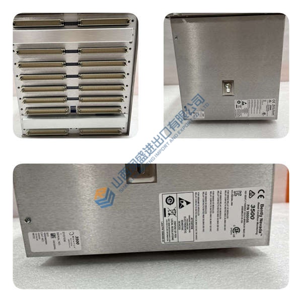
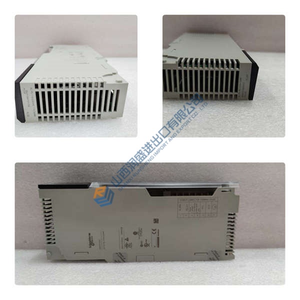
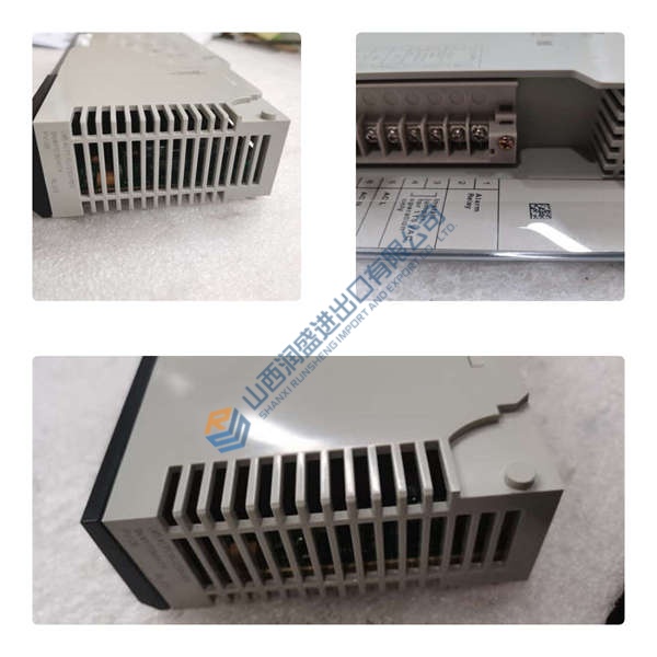
The ALSTOM TTM211 is a thyristor trigger module for the P320 AVR V2 excitation system, used to generate six firing pulses for a 3‑phase thyristor bridge in generator excitation. In power plant commissioning, this unit sits downstream of the AVR and drives the SCR bridge that regulates field current.
In P320 AVR V2 deployments, the TTM211 typically accepts a 4–20 mA setpoint from the regulator and synchronizes to the AC side of the thyristor bridge via PTs and filters. For exact supply range, firmware revision, and parameter maps, verify in the OEM commissioning guide and the module’s nameplate before installation.
Key Selling Points & Differentiators
- Deterministic 6‑pulse firing: individual gate control for each of the six SCRs in a PD3 bridge, aligned to synchronized AC references.
- Commissioning‑ready diagnostics: pulse fault detection, local mode control, and parameter tuning (e.g., CPH for phase compensation) per P320 procedures.
- Communication flexibility: RS485/RS232 with MODBUS supports integration with supervisor tools (Controcad/Cell Loader workflows).
- Test evidence available: we can share power‑on LED behavior, comms handshake logs, and a basic functional test report (photos/video on request).
- Versus generic trigger cards: the TTM211 is engineered for P320 AVR V2 parameter sets and redundancy schemes; do not use in non‑P320 racks without engineering approval.
- Not recommended for: systems requiring integrated time‑date stamping or non‑MODBUS fieldbus—this module has no time‑date feature and uses MODBUS for comms.
Frequently Asked Questions
Q1: Can I drop this TTM211 straight into my P320 AVR V2 rack?
A: Usually yes—if your system is a P320 AVR V2 build and the slot is for a TTM211. Action: photograph the nameplate, note the existing module’s firmware/parameters, and confirm the replacement’s revision matches before hot‑swap.
Q2: What bridge types does the module support?
A: Primary use is a 6‑thyristor 3‑phase full bridge (PD3). It can also control a 3‑thyristor mixed bridge or a 4‑thyristor full‑wave single‑phase bridge. Verify wiring and sync transformer connections per the project schematic.
Q3: How do you verify firmware and configuration before shipping?
A: We read and record available firmware/parameter identifiers, capture LED status and comms response, and log them in the test report. If your project requires specific parameters (e.g., CPH, MLOC), tell us up front—we’ll verify or advise on parameter loading.