
Description
Product Introduction
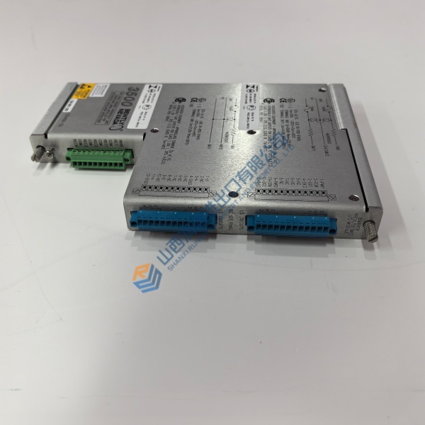
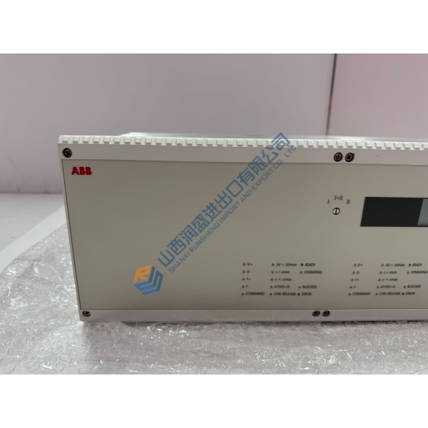
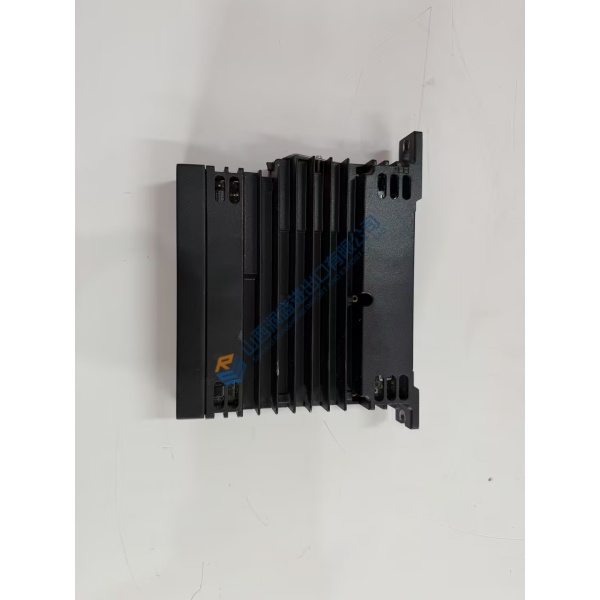
Need to restore high-torque motion control after a power stage failure? The BAUMÜLLER BM4463-FI1-01644-0310-SET delivers high-performance vector control for heavy-duty industrial machinery. Operating under IEC 61800-3 guidelines, this unit fits directly into existing b maXX cabinets without requiring cabinet frame modification.
In field deployments of b maXX 4000 series drives, this module maintains closed-loop position response down to sub-millisecond cycle times. The BAUMÜLLER BM4463-FI1-01644-0310-SET links directly into master fieldbus networks to keep main production lines operating smoothly. Listed prices serve as a reference baseline; actual costs depend on current global market availability. Contact our procurement team to get a formal quote and verify current lead times.
Installation & Configuration Guide
Phase 1 — Pre-Installation (est. 10 min)
Shut off main incoming three-phase power. Wait a full 15 minutes for intermediate DC bus capacitors to discharge down to safe levels below 50 V DC. Gather a metric hex key set, torque wrench, digital multimeter, and an ESD grounding strap. Export your parameter file using ProDrive software. Take high-resolution photos of DIP switches, fieldbus card jumpers, and terminal connections on the active BAUMÜLLER BM4463-FI1-01644-0310-SET unit.
Phase 2 — Removal (est. 5 min)
Label every control wire, encoder lead, and power line with wire tags before loosening terminals. Disconnect power cables from U, V, W, and DC bus bars. Release the heavy-duty cabinet mounting bolts securing the drive frame. Carefully lift the unit off its mounting rails, keeping it perpendicular to avoid damaging adjacent cabinet ducting. Inspect the mounting panel for heat stress marks or dust accumulation.
Phase 3 — Installation (est. 10 min)
Put on your ESD wrist strap and bond its lead to cabinet ground. Unpack the replacement BAUMÜLLER BM4463-FI1-01644-0310-SET from its protective anti-static packaging. Verify part numbers on the side rating plate. Match all option card DIP switch positions to the photos taken in Phase 1. Mount the drive securely onto the backplate and torque main structural bolts to specification. Reconnect power and signal cables, torquing high-current DC bus bolts to ~4.5 N·m. Perform a thorough wiring check.
Phase 4 — Power-On & Testing (est. 15 min)
Measure three-phase line-to-line voltage to verify 400–480 V AC before energizing main power. Apply 24 V DC auxiliary control power first. Observe LED status indicators: verify normal boot sequence without latched hardware faults. Connect your diagnostic laptop, launch ProDrive, and flash your saved parameter configuration to the drive. Perform a low-speed jog test on the motor. Monitor phase current balance and thermal rise for 30 minutes under load. Log the replacement drive serial number in your site records.
Quick Troubleshooting Reference
- No Display / LEDs Off: Check 24 V DC auxiliary power supply, verify control terminal plug connections, test primary fuses.
- DC Bus Overvoltage Fault: Check external braking resistor connection, verify braking chopper activation settings, inspect deceleration ramp times.
- Fieldbus Communication Failure: Verify station address settings on DIP switches, check bus cable termination, test fieldbus option card seating.



