Description
Product Introduction
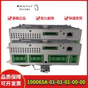
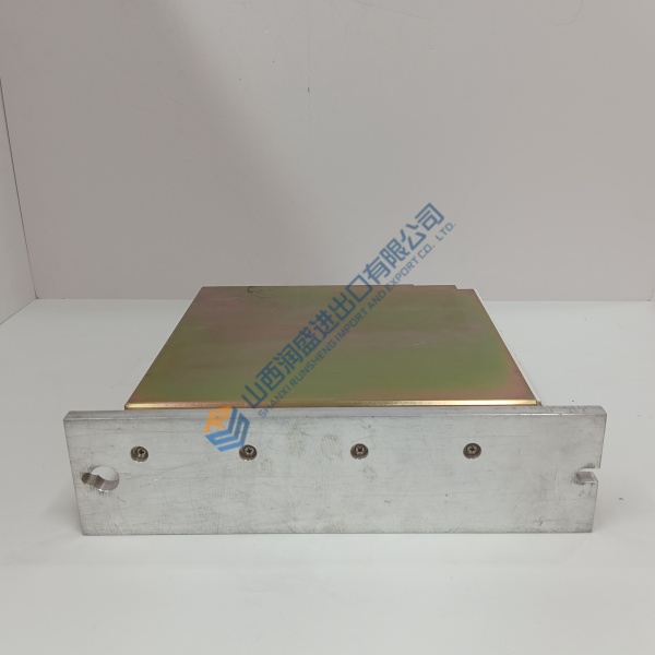
High-vibration machinery protection systems lose critical diagnostic capability when network interfaces fail or drop packet frames. The BENTLY 3500/22M-01-01-01 Transient Data Interface module eliminates these communication gaps by maintaining continuous data collection between rack monitors and system software.
Serving as the primary communications hub for the 3500 rack, this module collects steady-state and transient wave data for advanced machinery diagnostics. In my experience, upgrading or replacing a faulty interface with this module restores full System 1 software integration and stabilizes host network handshakes.
Installation & Configuration Guide
Phase 1 — Pre-Installation (est. 10 min): Power down the target 3500 rack or ensure rack bypass switches are engaged if working on live redundant systems. Gather a flat-head screwdriver, ESD wrist strap, and ethernet tester. Photograph the DIP switch configurations, jumper positions, and rear network wiring before pulling the existing unit.
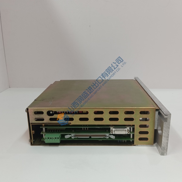
Phase 2 — Removal (est. 5 min): Disconnect Ethernet and serial cables from the rear I/O module. Unfasten the top and bottom retaining screws on the front panel, then pull the module straight out using the ejector levers to prevent backplane pin damage. Repeat the unfastening process for the rear I/O module if replacing both components.
Phase 3 — Installation (est. 10 min): Put on your ESD wrist strap before touching the circuit board. Verify the option codes on the module side label. Replicate all hardware switch settings from your initial photographs. Slide the main module into Slot 1 until it firmly seats in the backplane connector, then tighten the faceplate screws to 0.6 N·m.
Phase 4 — Power-On & Testing (est. 15 min): Supply power to the rack and monitor the front status LEDs (green OK LED steady). Connect a network cable from your laptop running 3500 Rack Configuration Software, establish a connection, and download the saved configuration file to the module. Verify real-time transient data throughput in System 1 for 30 minutes before returning the rack to active protection duty.
Troubleshooting Quick-Reference:
- OK LED OFF → Check rack power supply voltage; re-seat module in backplane.
- TX/RX LEDs inactive → Verify Ethernet cable link status and IP subnet configuration.
- Configuration load fails → Confirm software version supports 3500/22M firmware.
FAQ
Can I just drop this in and go? No, because a blank or replacement TDI contains no rack logic configuration. You must upload the original rack configuration file (.350 format) using 3500 Rack Configuration Software before the module can route data correctly.
Are the 3500/20 RIM and 3500/22M TDI directly pin-compatible? Well, technically the 3500/22M replaces the legacy 3500/20 Rack Interface Module (RIM), but you must also swap the rear I/O module to support the upgraded Ethernet interfaces.