Description
Product Introduction
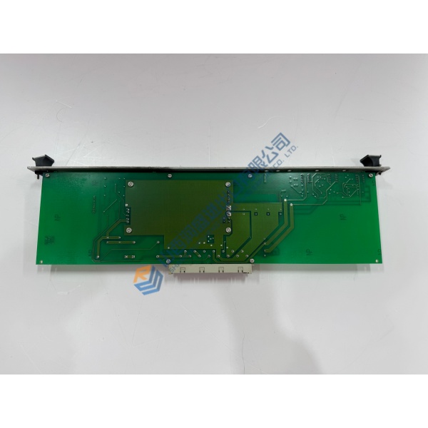
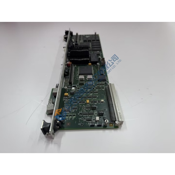
Unexpected shutdowns on centrifugal air compressors often originate from failed signal processing channels on aging control cards. The CAMERON AAP3798102-00030 circuit board eliminates these operational halts by delivering reliable signal conditioning across high-vibration turbomachinery environments.
Engineered specifically for Turbo-Air system architectures, this controller board maintains accurate sensor reading conversion and fast backplane data throughput. In my experience, replacing a degraded board with this unit stops nuisance trips and stabilizes pressure regulation on critical plant air headers.
Installation & Configuration Guide
Phase 1 — Pre-Installation (est. 10 min): De-energize the compressor control cabinet and wait 5 minutes for bus power to discharge completely. Assemble a torque screwdriver, antistatic wrist strap, and a digital multimeter. Photograph the DIP switch positions, jumper settings, and edge connector ribbon cabling before removing the existing unit.
Phase 2 — Removal (est. 5 min): Unplug all field wiring terminal blocks and ribbon connectors gently. Unscrew retaining fasteners on the card cage faceplate, then slide the controller out perpendicular to the backplane to prevent pin bending. Inspect the backplane bus socket for debris or damaged contacts.
Phase 3 — Installation (est. 10 min): Fasten your ESD grounding wrist strap. Verify the part number on the board label matches your bill of materials. Match all jumpers and DIP switch arrays to the original photographs. Slide the board smoothly into the rack guide slots until the backplane connector seats completely, then tighten faceplate screws to 0.4 N·m.
Phase 4 — Power-On & Testing (est. 15 min): Check cabinet DC voltage levels to confirm 24 V DC power supply stability. Apply system power and observe startup LEDs (green indicates normal boot sequence). Connect your diagnostic software interface, upload system parameters, and test I/O channel responses. Run the compressor through a 30-minute idle monitoring cycle to verify communication stability.
Troubleshooting Quick-Reference:
- No status LEDs after power-on → Verify 24 V DC supply polarity and check onboard protective fuses.
- System fault on boot → Inspect jumper configurations; verify firm backplane connector seating.
- Analog input drift → Check field wiring shield grounding at single-point terminal ground bar.
FAQ
Can I just drop this in and go? Not quite, because DIP switches and software calibration factors vary between specific compressor models. Match hardware jumpers to your old board and verify transducer zero-points in the panel menu before starting the motor.
Is the AAP3798102-00030 board compatible with older Vantage or Maestro panel revisions? Physical connector pinouts match across adjacent generations, but firmware revisions dictate actual software handshake compatibility. Check your panel firmware build prior to installation.