
Description
Product Introduction
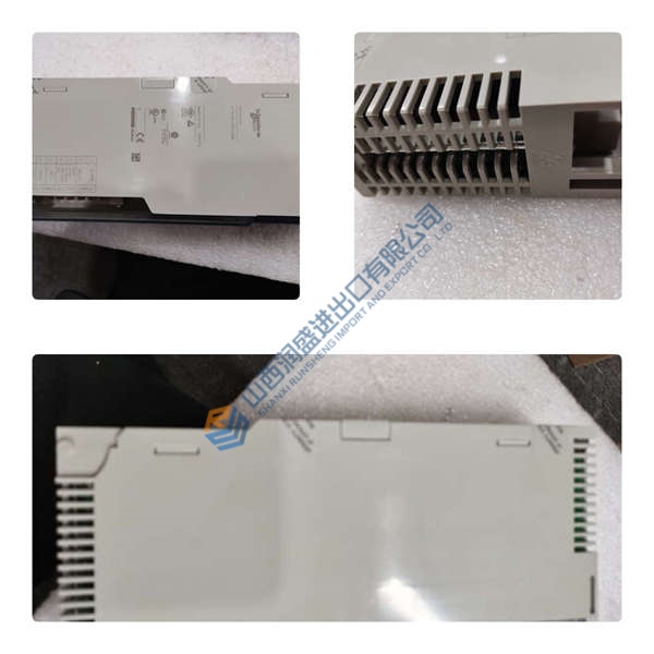
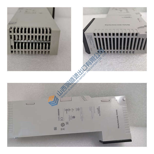
The ABB CS513 (3BSE000435R1) is an IEEE 802.3 LAN communication module designed for the Advant Master DCS family—specifically AC410, AC450, and AC460 process controllers. It provides the physical and data-link layer interface for the MasterBus 300/300E control network, enabling cyclic exchange of process values, setpoints, alarms, and interlock signals between controllers in the same rack or across distributed racks.
This module stands out for its dual-mode operation: a hardware DIP switch selects between standard MB300 topology and extended MB300E for larger network scale. In field deployments of Advant Master systems, we’ve seen link monitoring catch CRC errors in real time, preventing silent data corruption during high EMI events. The conformal-coated PCB and built-in surge suppression make it a solid choice for power plant and refinery environments where dust, oil mist, and voltage spikes are everyday realities.
Installation & Configuration Guide
Phase 1—Pre-Installation (est. 10 min)
De-energize the Advant Master rack and wait 5 min for capacitor discharge. Grab a Torx T20, wire strippers, and a Fluke 115 multimeter. Export your current Advant Control Builder project and photograph the existing module’s DIP switches, wiring, and rack position.
Phase 2—Removal (est. 5 min)
Label the DB15 MasterBus cable before disconnecting. Release the DIN-rail latch, pull the module straight out perpendicular to the backplane, and inspect the backplane connector pins for bent contacts or corrosion.
Phase 3—Installation (est. 10 min)
Strap on your ESD wristband. Verify the part number matches CS513 3BSE000435R1. Replicate the DIP switch settings from your photos—MB300 (position 1) or MB300E (position 3). Seat the unit until the latch clicks, reconnect the DB15 cable, torque terminal screws to ~0.5 N·m, then run a pre-power checklist: backplane continuity, 24 V DC supply polarity, ground bond.
Phase 4—Power-On & Testing (est. 15 min)
Verify supply voltage is 24 V DC (±10%). Power up and watch the LEDs: green = RUN, red flash = ERR, amber flash = DIAG. Hook up Advant Operator Workplace or Control Builder, download the MasterBus configuration, then run a full I/O loop test. Log at least 30 min of stable operation before signing off.
Troubleshooting quick-reference:
- No comms → check DB15 cable, switch port, termination resistor
- ERR steady → firmware mismatch; attempt update via Control Builder
- Download fails → verify cable and software version
- Over-temperature → check 100 mm clearance above/below, 30 mm sides



