
Description
Product Introduction
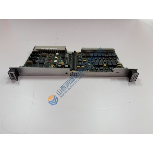
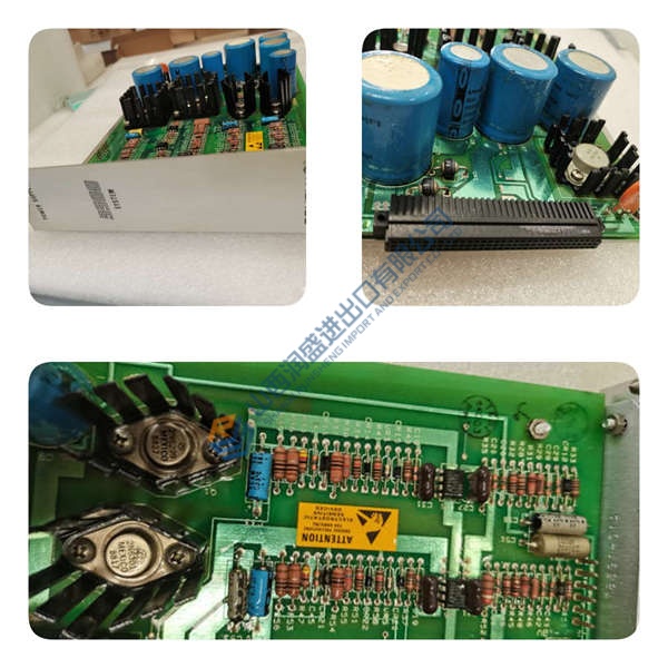
Spurious thyristor firing errors in heavy industrial drive cabinets typically stem from a failing main processor card. The DDC779AE1 3BHB006805R0001 ABB drive control board resolves timing drift and signal degradation by executing high-speed digital control algorithms across medium-voltage drives and excitation systems. Designed for demanding industrial environments, this central processing card manages real-time converter gating loops, maintaining tight current regulation within ±0.1% under heavy load fluctuations.
Field operations across rolling mills and utility excitation plants confirm that switching to a calibrated control board maintains firing pulse precision within 0.5 ms. Replacing a degraded processing unit restores stable field current regulation and eliminates nuisance converter trip alarms. Honestly, running worn digital control boards in high-power applications is a risk that leads to expensive forced outages. This unit ships fully pre-tested from surplus warehouse stock, allowing maintenance engineers to clear drive fault codes before scheduled plant restarts.
Key Technical Specifications
- Parameter: Value
- Part Number: 3BHB006805R0001
- Hardware Code: DDC779AE1
- Manufacturer: ABB
- System Family: MEGAPACK / UNITROL Excitation & Drive Systems
- Module Type: Main Controller / Digital Drive Control Board
- Logic Voltage: 24 V DC (18 to 30 V DC operational range)
- Signal Interfaces: High-speed fiber-optic gate driver links
- Operating Temperature: −10 to +65 °C (14 to 149 °F)
- Mounting Style: Chassis rack panel slot mount
- Isolation Rating: Optical isolation between control logic and power stage
- Environmental Protection: Conformal coated circuit boards for harsh environments
Installation & Configuration Guide
Phase 1 — Pre-Installation (est. 10 min) De-energize the main drive cabinet supply breaker completely. Wait 5 minutes for high-voltage DC link capacitors to discharge safely below 50 V DC. Gather an ESD grounding wrist strap, insulated screwdriver set, and a digital multimeter. Save existing parameter sets from the drive panel software workstation. Photograph all wire locations, fiber-optic routing paths, and onboard DIP switch settings before touching the original card.
Phase 2 — Removal (est. 5 min) Disconnect optical cables carefully by pressing the connector release tabs. Mark all copper terminal plugs before pulling them from the board header. Unfasten retaining screws located at the module faceplate corners. Slide the card straight out along its guide tracks, taking care not to bend backplane connector pins against adjacent framework.



