
Description
Product Introduction
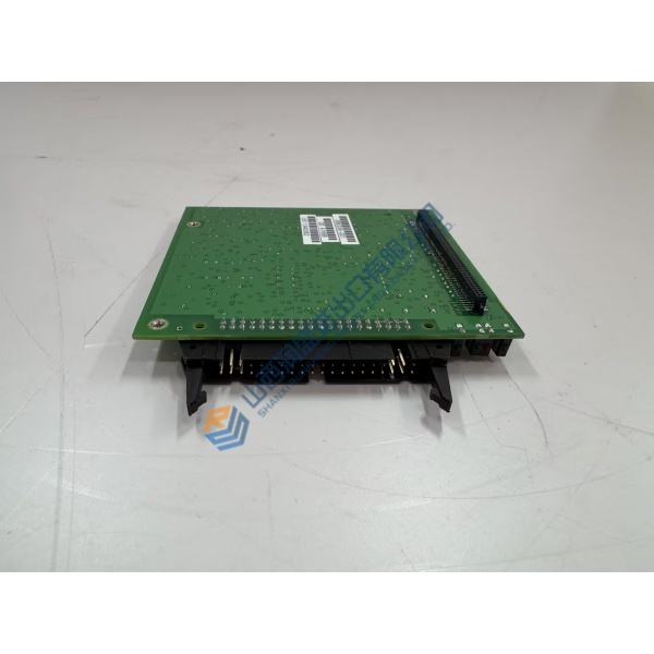
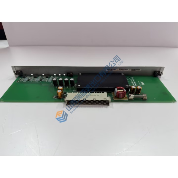
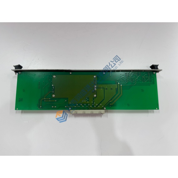
Complex multi-axis machines demand deterministic servo and stepper control with flexible I/O. The Delta Tau PMAC2-PCI is a full-sized PCI motion controller optimized for sine-wave or direct-PWM servo amplifiers and pulse-and-direction stepper drives. It can operate inside a host PC via the PCI bus or run completely standalone through its RS-232/RS-422 serial port.
The base board provides four channels of on-board axis interface circuitry (expandable) with configurable command outputs, differential/single-ended encoder inputs, and extensive digital I/O. Servo algorithms include PID with notch and feed-forward terms. Higher-speed CPU and Turbo options extend capability to more axes and denser memory. Listed price is reference only—request a quote for current market conditions.
Installation & Configuration Guide
Phase 1 — Pre-Installation (est. 10–15 min)
Power down the host PC and discharge residual voltage. Tools: ESD wrist strap, anti-static mat, PEWIN or equivalent software, documentation of existing jumpers and I-variables. Photograph the board orientation, all connectors (JTHW, JEQU, machine ports, serial) and any Acc-24 expansion cards.
Phase 2 — Removal (est. 5–10 min)
Label every cable. Disconnect the PCI edge connector, serial port, encoder/amplifier cables and any expansion links. Carefully withdraw the board (note the piggyback CPU occupies part of the adjacent slot). Inspect the slot and connectors.
Phase 3 — Installation (est. 10–15 min)
Confirm the part number and CPU option match the application. Set any required jumpers per the hardware reference. Seat the board fully in the PCI slot, reconnect all cables exactly as photographed, and secure the bracket.
Phase 4 — Power-On & Testing (est. 20–30 min)
Power the system. Verify PCI enumeration or serial communication. Load or verify the project in PEWIN, check encoder feedback, command-output polarity and limit flags. Jog axes at low speed, verify following error and safety functions. Run stable and log the change.
Troubleshooting quick-reference:
- Board not detected → check PCI slot, power and dual-port RAM option
- No encoder counts → verify differential wiring and termination
- Amp enable fails → check output configuration (PWM vs pulse/dir) and flags



