Description
Product Introduction
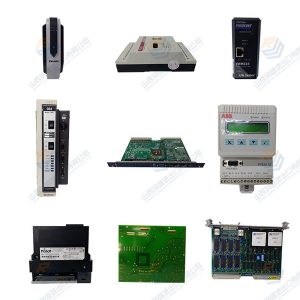
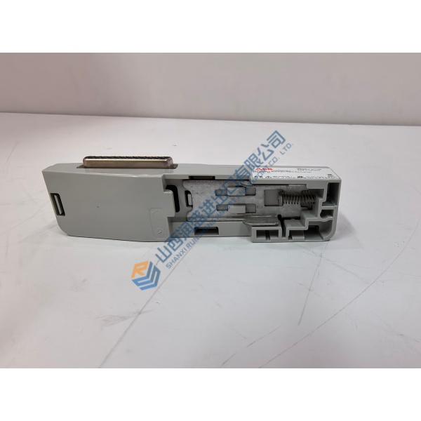
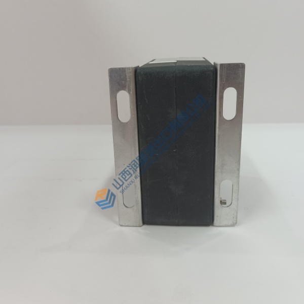
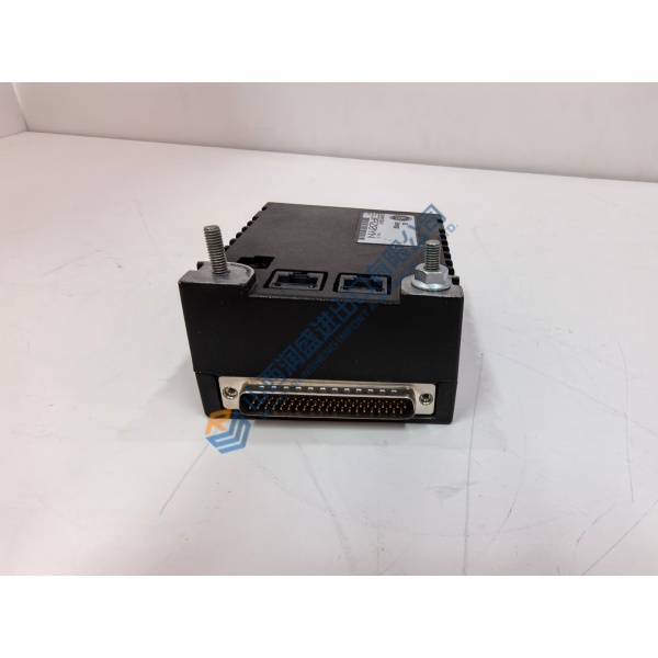
Looking to eliminate system downtime caused by a failed main processor card? The EMERSON P152.R4 handles high-speed logic processing and real-time signal distribution across legacy industrial power setups. Built to comply with IEC 61131 standards, it drops directly into standard rack backplanes without requiring wiring changes.
In field deployments of Emerson control systems, this module maintains deterministic signal scanning down to sub-millisecond intervals. The EMERSON P152.R4 interfaces directly with system power components to keep critical processing lines running smoothly. Listed prices serve as a general baseline reference; actual pricing depends on current market availability. Contact our sales team directly to request an exact quote and confirm current delivery schedules.
Installation & Configuration Guide
Phase 1 — Pre-Installation (est. 10 min)
Turn off all main cabinet power sources. Wait 5 minutes for internal filter capacitors to discharge completely. Assemble a flathead screwdriver, ESD grounding wrist strap, and digital multimeter. Before removing the existing unit, export and back up your current system configuration file using your programming software. Take clear photos of all DIP switch arrays, jumper blocks, and wiring connections on the active EMERSON P152.R4 card.
Phase 2 — Removal (est. 5 min)
Label every signal wire and cable assembly with wire tags before loosening terminal connections. Disconnect interface cables by pulling on the connector body rather than the wires. Disengage the top and bottom rack retaining clips. Pull the module straight out perpendicular to the backplane to avoid bending connector pins. Inspect the backplane socket for dust, debris, or thermal stress marks.
Phase 3 — Installation (est. 10 min)
Put on your ESD wrist strap and attach its lead to a verified chassis ground point. Remove the replacement EMERSON P152.R4 from its anti-static shielding bag. Check the revision code against your work order. Align every DIP switch and jumper block to match the reference photos taken in Phase 1. Slide the card smoothly along the rack guide rails until the backplane connector seats with a firm click. Tighten retaining screws to ~0.5 N·m torque. Reconnect all signal wires according to your terminal labels. Perform a visual connection check.
Phase 4 — Power-On & Testing (est. 15 min)
Check incoming supply voltage across terminals — verify 24 V DC ±10% before powering up the rack. Turn on main power. Observe the LED boot sequence: PWR should show steady green, RUN turns green after passing self-checks, while ERR remains off. Connect your PC via the diagnostic port, establish a communication link, and upload your saved parameter file. Execute a single-loop signal test across connected I/O points. Monitor the module under live idle conditions for 30 minutes to confirm stability. Record the serial number swap in your site maintenance database.
Quick Troubleshooting Reference
- No Communication: Verify RS-485 polarity (A/B lines), check station address switch settings, test cable continuity.
- ERR LED Flashing Red: Hardware self-test failure or memory checksum mismatch; re-download parameter file or cycle power.
- Download Fails: Verify software baud rate settings, check diagnostic cable pinouts, confirm option jumpers match protocol requirements.