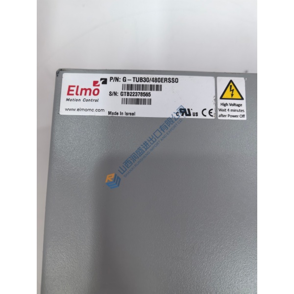
Description
Product Introduction
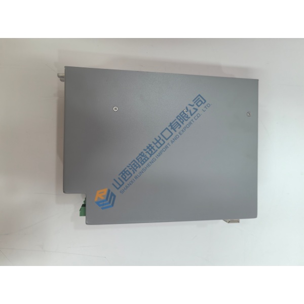
Emerson ROC809 is a modular remote operations controller and gas flow computer for field measurement, PID control, logic sequencing, data logging, and remote communications in oil and gas facilities.
The platform provides nine module slots, supports up to 12 meter runs, and includes built-in LOI, Ethernet, and RS-232 ports. Older Series 1 and newer Series 2 hardware are not interchangeable in every configuration, so verify the CPU generation and firmware before replacement.
The ROC809 platform has both Series 1 and Series 2 hardware. Series 2 increases processor speed from 50 MHz to 65 MHz, flash memory from 4 MB to 16 MB, DRAM from 8 MB to 16 MB, and user-program memory capacity.manuals
A Series 2 CPU can fit the fixed ROC809 Series 1 backplane, but that does not automatically provide every Series 2 function. Firmware and module-placement rules still apply. Confirm the complete hardware combination before purchase.manuals
Installation & Configuration Guide
Phase 1—Pre-Installation — estimated 15 minutes
De-energize the ROC809 and connected field circuits. Wait at least 5 minutes for discharge before removing the CPU, power module, communication module, or I/O module.
Prepare:
- ESD wrist strap and grounded ESD mat.
- Fluke 115 multimeter.
- Insulated screwdriver set.
- ROCLINK 800 laptop connection.
- Current ROC809 configuration backup.
- Firmware and CPU-series records.
- License-key records.
- Camera for module positions, wiring, and labels.
Export the ROCLINK 800 configuration, historical-data requirements, event and alarm settings, meter-run parameters, communication settings, FST logic, and license information. Record the power module type: PM-12, PM-24, or PM-30.
Photograph the CPU label, module sequence, wire channels, terminal blocks, communication cables, and DIN-rail mounting arrangement.
Phase 2—Removal — estimated 10 minutes
Label every field wire and communication cable before disconnecting them. Record each module’s slot position. Optional communication modules belong in the first three available module slots; I/O modules follow the applicable slot rules.
Release the module retaining screws and pull each module straight from the backplane. Do not bend the board or apply lateral force to the connector.
Inspect the backplane and module connectors for bent contacts, corrosion, contamination, discoloration, or heat damage. Retain the original CPU until the replacement has passed configuration and measurement checks.
Phase 3—Installation — estimated 15 minutes
Apply ESD protection before opening the replacement packaging. Verify the ROC809 model, CPU series, power module, I/O modules, communication modules, firmware, license keys, and hazardous-area approval against the procurement record.
Install the CPU and modules in the documented positions. Tighten retaining screws without over-torquing. Reconnect wiring according to the approved terminal diagram.