Description
Product Introduction
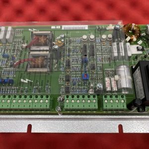
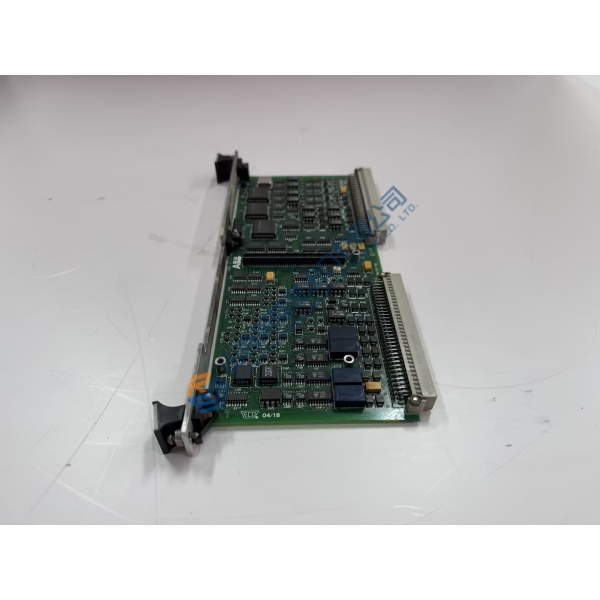
Connecting field instruments across legacy serial networks often leads to dropped packets and signal latency inside busy processing plants. The FBM230 FOXBORO fieldbus interface module solves this integration bottleneck by hosting four independent, galvanically isolated serial channels on a single baseplate slot. Built for Foxboro I/A Series and Foxboro EVO DCS architectures, this fieldbus interface unit converts Modbus RTU and custom serial protocols into standard control network data, maintaining cyclic field updates within a tight ±0.5 ms window under heavy device polling.
Field engineering reports from chemical processing facilities demonstrate that installing a fresh interface module restores clean multi-drop communications across all four ports immediately. Swapping out a degraded serial card eliminates intermittent channel dropouts and keeps field instrument telemetry flowing back to your control stations. To be frank, relying on aging serial interface cards in critical safety or custody transfer loops is an unnecessary risk during peak production runs. This unit ships pre-tested from surplus warehouse stock, enabling site engineers to restore reliable fieldbus communications before scheduled plant turnarounds.
Key Technical Specifications
- Parameter: Value
- Part Number: FBM230 (P0926KM)
- Manufacturer: Foxboro / Schneider Electric
- System Family: I/A Series / Foxboro EVO DCS
- Module Type: Four-Port Fieldbus Interface Module
- Input Voltage: 24 V DC (nominal via baseplate backplane)
- Power Dissipation: 7.5 W maximum under full 4-port operation
- Serial Communication Ports: 4 galvanically isolated channels (RS232, RS422, or RS485)
- Baud Rates: Configurable up to 38.4 kbps per channel
- Operating Temperature: −20 to +70 °C (−4 to +158 °F)
- Mounting Format: Standard Foxboro DIN rail baseplate slot
- Isolation Rating: 1,500 V AC field-to-bus galvanic isolation
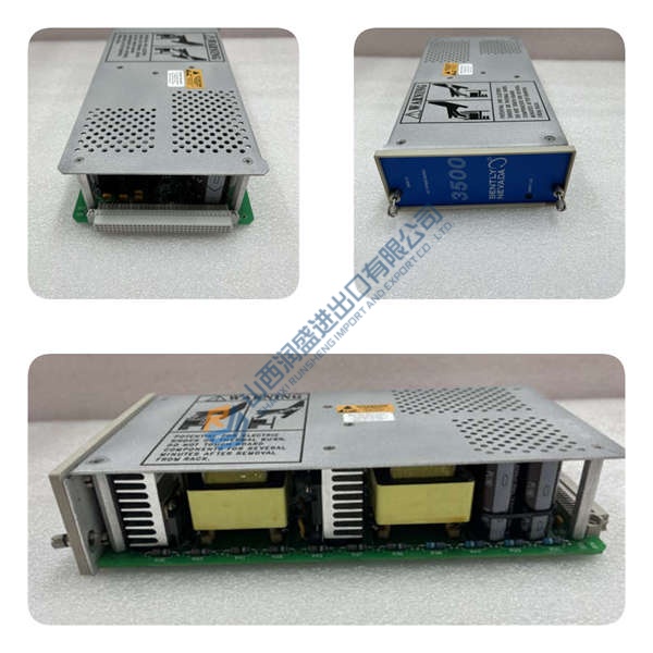
Installation & Configuration Guide
Phase 1 — Pre-Installation (est. 10 min) Disconnect power to the local baseplate assembly. Wait 5 minutes for power supply filter capacitors to discharge fully. Gather a flathead screwdriver, an ESD grounding wrist strap, and a digital multimeter. Save your current block configuration files using Foxboro I/A Series Letterbug / ICC software. Photograph all field wiring connections on the termination assembly (TA) and note channel address settings on the baseplate slot before touching the hardware.
Phase 2 — Removal (est. 5 min) Loosen the upper and lower faceplate mounting screws securing the card to the baseplate. Pull the module release latches outward simultaneously to disengage the rear connectors. Slide the board straight out along the baseplate slot guides, keeping it perpendicular to avoid bending backplane connector pins.
Phase 3 — Installation (est. 10 min) Attach your grounded ESD wrist strap before handling the replacement hardware. Confirm the FBM230 FOXBORO part number label on the side casing matches your engineering specification. Align the module with the baseplate slot guides, push firmly until the rear edge connectors lock into the baseplate, and torque mounting screws to 0.5 N·m before reconnecting field cable plugs.
Phase 4 — Power-On & Testing (est. 15 min) Reapply 24 V DC power to the baseplate. Observe the front diagnostic status LEDs: the green READY indicator must illuminate solid, while red FAIL lights should extinguish after boot self-tests finish. Open your I/A Series workstation, verify the module Letterbug assignment, and check communication status across all four serial ports. Perform a loopback or field device read test on each channel to confirm data flow stability before returning the slot to active scanning.
Troubleshooting Quick-Reference
- FAIL LED Solid Red: Hardware boot check error or firmware mismatch. Attempt a cold baseplate restart and re-assign the slot Letterbug.
- Port Comm Timeout: Check RS485 polarity (A/B lines) and termination resistors on the TA block using a Fluke 115 multimeter.
- Module Not Recognized: Inspect rear baseplate edge pins for dust or physical damage. Re-seat the card firmly into its baseplate slot.
Quality Transparency
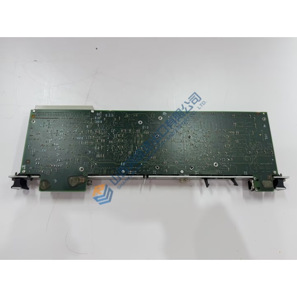
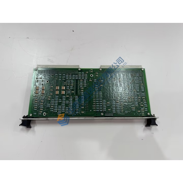
Incoming Inspection: We verify source documentation, factory packing manifests, and customs paperwork for full origin validation. Anti-counterfeit checks involve inspecting PCB trace topology, component dates, and factory security labels under magnification. Technicians examine the circuit board for solder fatigue, track repair marks, component yellowing, or edge connector oxidation. All faceplate hardware and accessories are checked against factory parts lists.
Live Functional Test: Boards go through a benchtop power-on self-check where diagnostic startup codes are logged. We mount the module into a Foxboro I/A Series baseplate test rig to verify communication handshakes across the Fieldbus. Signal generators simulate 4-port Modbus RTU serial traffic across RS232, RS422, and RS485 modes. The board runs inside an environmental chamber at elevated temperature for over 24 hours under continuous load, with thermal metrics logged into a formal Test Report upon completion.