Description
Product Introduction
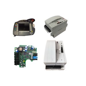
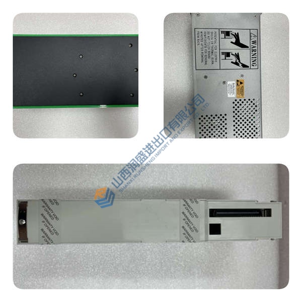
The Foxboro FBM232 Field Device System Integrator module links external serial networks directly into Foxboro I/A Series and EcoStruxure control architectures. Fitting standard DIN rail baseplates, the card translates third-party protocol registers into standard DCS compound tags. Bottom line — it works. (Keyword #1)
Executing driver stacks on dedicated onboard processors, the card prevents communication latency from slowing control bus traffic. Featuring galvanic isolation across four independent serial channels, the device operates stably up to 115.2 kbps under high ambient electrical noise. Honestly, running dual redundant module pairs on a single baseplate is actually clever for preventing lost telemetry during instrument port failures.
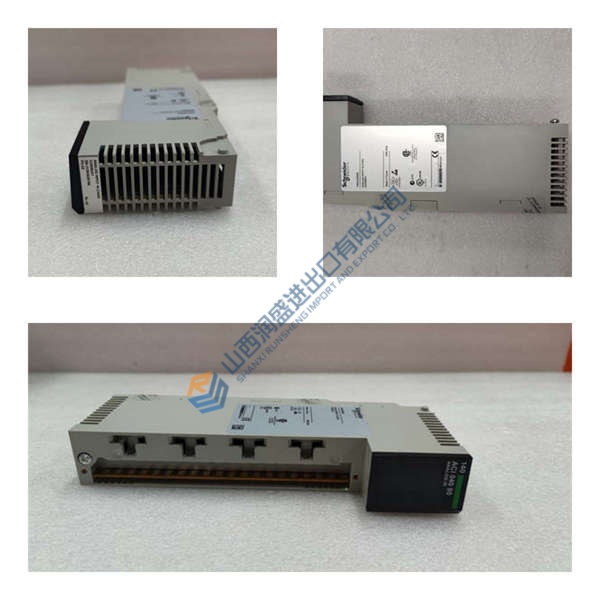
Pricing & Availability Note: Listed pricing is for reference only; actual unit cost depends on market supply and order quantity. Request an official quote to check current stock for the Foxboro FBM232. (Keyword #2)
Installation & Configuration Guide
Phase 1 — Pre-Installation (est. 10 min)
- Turn off power feeds supplying the target DIN rail baseplate.
- Wait 5 minutes to let filter capacitors bleed down completely.
- Bring a slotted terminal driver, anti-static grounding strap, and Fluke 115 multimeter.
- Export active I/A Series letterbug settings and take photos of existing TA cable terminations.
Phase 2 — Removal (est. 5 min)
- Loosen top and bottom baseplate retention screws.
- Unplug termination assembly (TA) cables attached to the front connectors.
- Squeeze the red module release latches at the top and bottom.
- Pull the module perpendicular to the baseplate edge connector.
Phase 3 — Installation (est. 10 min)
- Strap an ESD band onto your wrist and clip it to metal frame ground.
- Verify the side label on the module matches part number Foxboro FBM232 P0926GW. (Keyword #3)
- Align module guide rails with slot tracks on the baseplate.
- Push firmly until upper and lower retaining latches click into place.
- Reconnect TA cables and tighten mounting thumbscrews to 0.5 N·m torque.
Phase 4 — Power-On & Testing (est. 15 min)
- Re-apply 24 V DC main supply power to the baseplate assembly.
- Check front LEDs during boot (green READY LED solid / amber COMM LED flashing).
- Open Foxboro System Manager software to assign the letterbug address.
- Download the FDSI configuration file down to the target slot.
- Monitor Modbus register polling for 30 minutes to confirm continuous data flow.