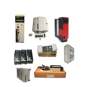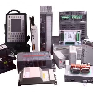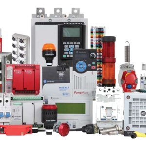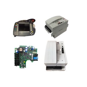
Description
Product Introduction
The Honeywell FS-FEEDER-24R is a redundant 24 V DC power feeder module designed for safety instrumented systems (SIS), fire alarm control panels, and emergency shutdown (ESD) systems where uninterrupted power is critical. It accepts two independent 24 V DC input sources (from UL-listed fire power supplies such as FS-PWR-24 or plant UPS) and delivers a single regulated 24 V DC output to safety loads—solenoids, relays, beacons, and control modules.
This unit stands out for its diode-OR redundancy architecture—two 130 A Schottky diodes isolate the inputs, so if one source fails, the other seamlessly takes over with <1 ms transfer time. In field deployments of Honeywell safety systems, we’ve seen zero voltage droop during source switchover, even with 10 A continuous loads. The 1500 V AC isolation between inputs and output, combined with 95 mm² (AWG 3/0) input terminals, makes it a solid choice for high-current, noise-immune power distribution in refineries, chemical plants, and offshore platforms where voltage spikes and ground loops are everyday realities.
Installation & Configuration Guide
Phase 1—Pre-Installation (est. 10 min)
De-energize both 24 V DC input sources and wait 5 min for capacitor discharge. Grab a Torx T20, wire strippers, and a Fluke 115 multimeter. Export your current power distribution diagram and photograph the existing module’s terminal wiring, fuse, and DIN-rail position.
Phase 2—Removal (est. 5 min)
Label every cable before disconnecting—Input A/B +/−, Output +/−, relay contact. Release the DIN-rail latch, pull the module straight out perpendicular to the rail, and inspect the backplane connector pins for bent contacts or corrosion.
Phase 3—Installation (est. 10 min)
Strap on your ESD wristband. Verify the part number matches FS-FEEDER-24R. Replicate the terminal block wiring from your photos—Input A/B polarity, Output polarity, relay contact. Seat the unit on the DIN rail, torque M5 terminal screws to 10 Nm, reconnect all cables, then run a pre-power checklist: backplane continuity, 24 V DC supply polarity, ground bond.
Phase 4—Power-On & Testing (est. 15 min)
Verify supply voltage is 24 V DC (±10%) on both inputs. Power up Input A first, then Input B. Watch the relay contact—should close when both inputs are healthy. Measure output voltage—should be 24 V DC ±5%. Log at least 30 min of stable operation before signing off.
Troubleshooting quick-reference:
- No output → check input fuses, diode-OR board, terminal torque
- Output low → check input voltage droop, diode forward voltage drop (≤1.5 V)
- Relay open → check coil resistance (6.6 mA at 24 V DC), contact weld
- Over-temperature → check 100 mm clearance above/below, 30 mm sides