Description
Product Introduction
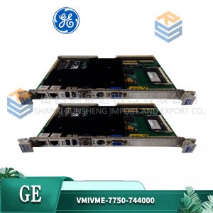
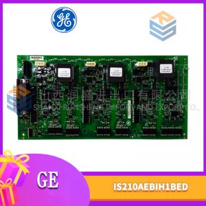
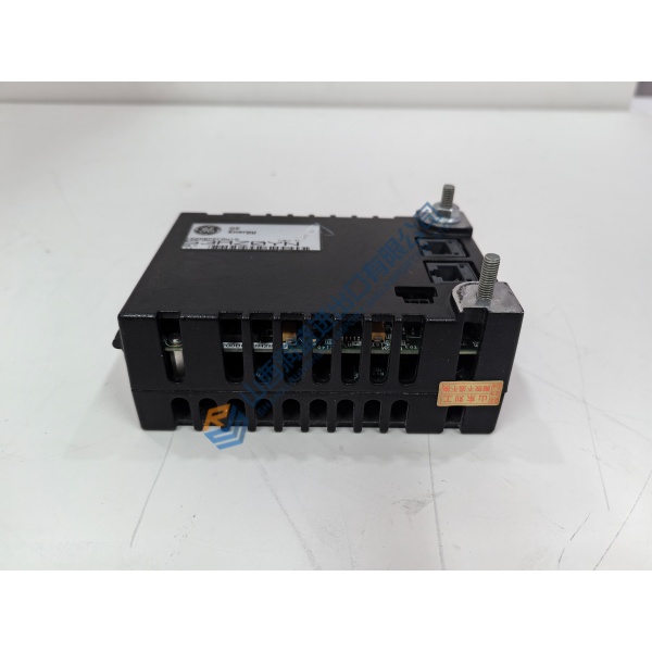
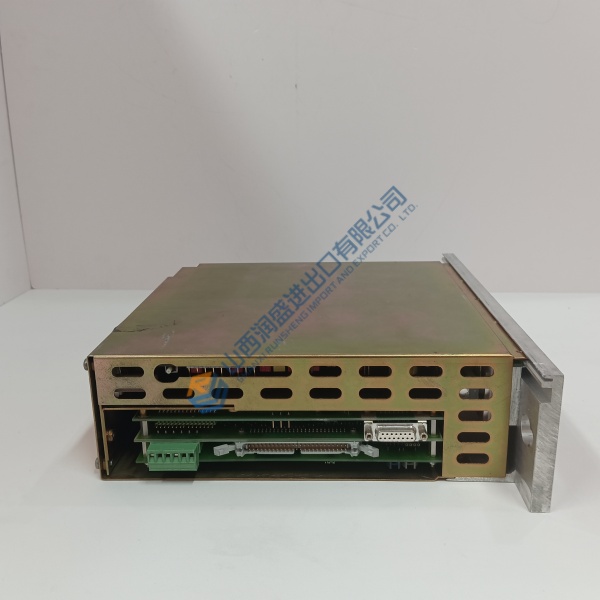
Troubleshooting a sudden logic trip on an active turbine panel? The GE 151X1207CK02SA01 handles high-speed signal processing and real-time control routines across legacy industrial power configurations. Designed around ISA-88 modular standards, this card drops directly into existing rack assemblies without needing backplane modifications.
In field deployments of Speedtronic control hardware, this module maintains precise signal sampling across demanding operating environments. The GE 151X1207CK02SA01 links directly into system backplanes to keep heavy power equipment running smoothly. Listed prices serve as a baseline reference; actual pricing depends on global market availability. Contact our procurement team directly to request an exact quote and check current delivery options.
Installation & Configuration Guide
Phase 1 — Pre-Installation (est. 10 min)
De-energize main panel power feeds. Wait 5 minutes for bus filter capacitors to discharge completely. Assemble a card puller tool, flathead screwdriver, ESD grounding wrist strap, and digital multimeter. Export your current control parameters using your configuration software. Take high-resolution photos of all DIP switch blocks, jumper matrices, and wiring connections on the active GE 151X1207CK02SA01 board.
Phase 2 — Removal (est. 5 min)
Tag all wire bundles with markers before disconnecting edge terminals. Unplug signal connectors by pulling directly on the shell body to protect pin solder joints. Release top and bottom card retention latches. Pull the module straight out along its guide tracks to avoid bending backplane pins. Inspect the rack slot for dust buildup or thermal discoloration.
Phase 3 — Installation (est. 10 min)
Put on your static wrist strap and connect its grounding clip to the enclosure frame. Remove the replacement GE 151X1207CK02SA01 from its static shielding bag. Check revision markings against your work order. Match every DIP switch position and jumper setting to the photos taken in Phase 1. Align the board with the rack guides and press firmly until the edge connector locks in. Tighten retaining screws to ~0.5 N·m torque. Reconnect all signal wiring according to your labels. Perform a visual connection check.
Phase 4 — Power-On & Testing (est. 15 min)
Verify incoming 24 V DC logic power with a multimeter before turning on main breakers. Apply power. Observe onboard LEDs: verify power indicators light up steady while error indicators stay off. Connect your PC interface, launch diagnostic software, and establish communication. Download the system parameter configuration. Execute a single-loop signal test across connected input channels. Monitor board stability for 30 minutes under idle conditions. Record the card replacement details in your maintenance log.
Quick Troubleshooting Reference
- No Communication: Verify edge connector seating, check serial/bus port settings, test signal line continuity.
- Fault LED On: Firmware mismatch detected or memory check error; re-download parameter file or cycle power.
- Signal Drift / Error: Inspect jumper configurations, verify shield grounding connections, clear diagnostic fault registers.