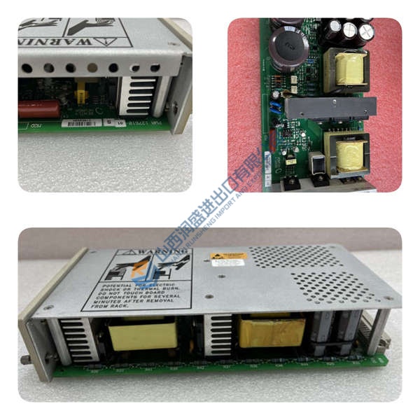
Description
Product Introduction
Facing an unexpected motor trip on a critical compressor or mill often traces back to inadequate thermal protection or missing real-time data. The GE 469-P5-HI-A1-T is a drawout motor management relay built for medium and large horsepower motors, integrating overload curves, RTD bias, differential protection options, and full metering in one chassis.
With 5 A CT inputs and the HI power supply range, this unit handles industrial control voltages while the Ethernet port supports Modbus TCP/IP alongside the dual RS485 ports. In field use the thermal model with unbalance bias cuts nuisance trips; six Form-C relays cover trip, alarm, and start-block functions. Listed price is reference only—request a quote for current market conditions.
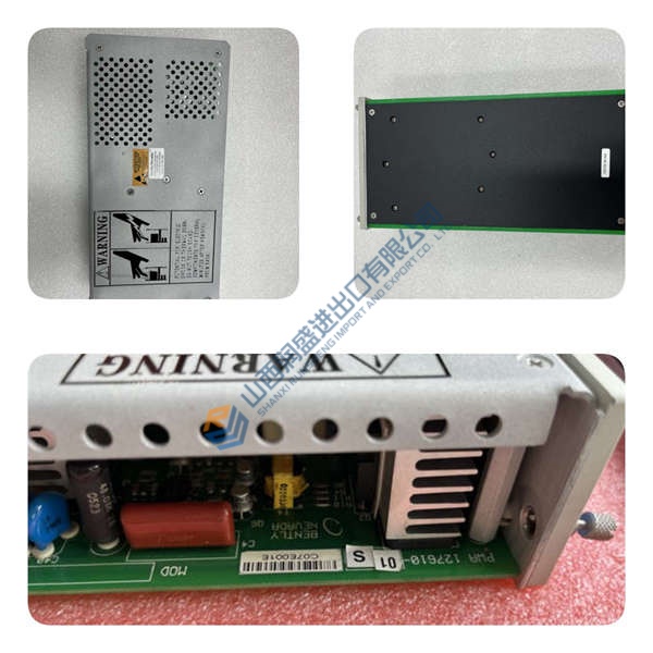
Installation & Configuration Guide
Phase 1 — Pre-Installation (est. 10 min)
De-energize the panel and wait a full 5 minutes for residual discharge. Gather tools: insulated screwdriver, torque wrench, Fluke 115 multimeter, laptop with EnerVista 469 software. Export the existing program and settings. Photograph every DIP switch, jumper, wiring terminal, and the rack layout before touching anything.
Phase 2 — Removal (est. 5 min)
Label every wire. Release the drawout latch, pull the unit straight out perpendicular to the backplane. Inspect the case connector pins for bent or corroded contacts. Automatic CT shorting protects the circuit while the relay is withdrawn.
Phase 3 — Installation (est. 10 min)
Wrist strap on first—ESD kills these boards fast. Verify the part number matches 469-P5-HI-A1-T. Replicate the photographed DIP/jumper settings exactly. Seat the unit until the latch clicks. Reconnect wiring to ~0.5 N·m. Run the pre-power checklist: correct control voltage range, CT polarity, VT configuration.
Phase 4 — Power-On & Testing (est. 15 min)
Confirm supply is within 90–300 V DC or 70–265 V AC. Watch LEDs: green = RUN, red flash = ERR, amber flash = DIAG. Connect EnerVista, download the program, exercise every I/O point, one full control loop, and communications. Let it run stable for >30 min. Log the swap in the maintenance record.
Troubleshooting quick-reference:
- No comms → check IP, cable, switch port, and baud rate
- ERR steady → firmware mismatch; verify version before update
- Download fails → cable integrity and software version match