Description
Product Introduction
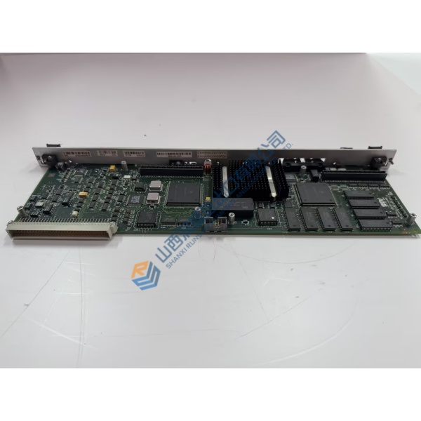
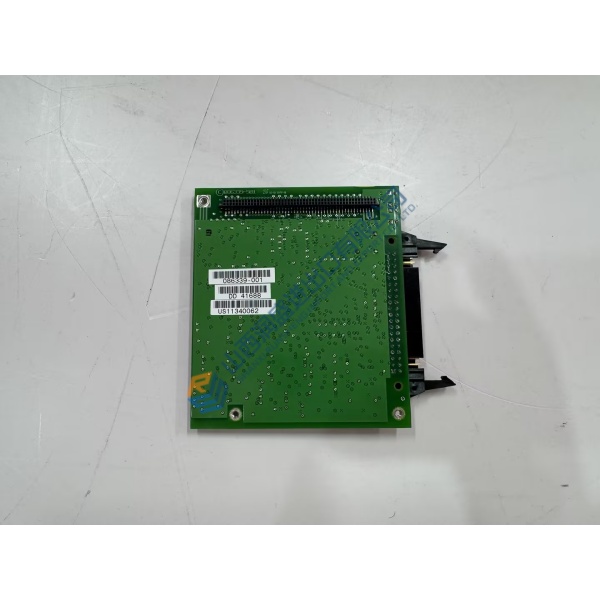
Gas turbine trips caused by noisy temperature readings or drifting servo position inputs disrupt power generation schedules without warning. The GE DS200ADMAH1AA analog submodule board resolves signal conversion errors by maintaining clean analog-to-digital processing across harsh turbine hall environments.
Designed to mount directly onto main Mark V processor cards, this board filters low-level sensor inputs and feeds stable data to control loops. In my experience, replacing a drifted analog card with this module stops false sensor alarms and restores accurate fuel valve control.
Installation & Configuration Guide
Phase 1 — Pre-Installation (est. 10 min): Power down the turbine control panel and open circuit breakers supplying the target rack. Wait 5 minutes for bus energy to clear. Gather a nut driver set, antistatic wrist strap, and a digital multimeter. Photograph all ribbon cables, standoff mounting locations, and DIP switch settings before removing the original board.
Phase 2 — Removal (est. 5 min): Unplug ribbon cable connectors carefully by squeezing side locking tabs. Unfasten the corner mounting standoffs securing the daughterboard to the base card, then lift the board straight up to prevent pin bending on multi-pin headers. Inspect multi-pin sockets for dust or bent contacts.
Phase 3 — Installation (est. 10 min): Put on an ESD grounding strap before opening the protective bag. Verify the full part number and revision code match your engineering drawing. Match all hardware DIP switch banks and jumper locations to your initial photographs. Align header pins with the base card socket, press straight down until fully seated, and tighten mounting standoffs to 0.4 N·m.
Phase 4 — Power-On & Testing (est. 15 min): Apply system logic power and check panel supply voltage stability (confirm 24 V DC and 5 V DC bus limits). Observe core status display LEDs for normal boot sequences. Connect your Mark V operator interface workstation, execute a signal calibration check on affected channels, and monitor loop stability for 30 minutes before enabling trip circuits.
Troubleshooting Quick-Reference:
- Analog input channel fault → Check ribbon cable connection alignment; re-seat multi-pin header.
- Diagnostic error on boot → Inspect jumper configurations; verify base card firmware compatibility.
- Signal calibration drift → Test field sensor wiring shielding and single-point ground connection.