Description
Product Introduction
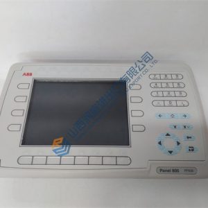
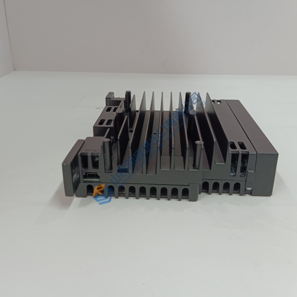
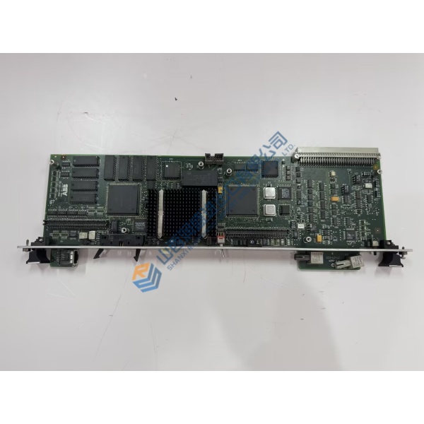
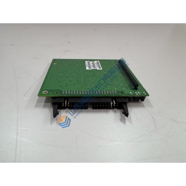
Failed SCR firing circuits or degraded pulse transformers in heavy industrial drive systems cause immediate phase imbalances and overcurrent trips. The GE DS200FCGDH1ABA gate drive board resolves these power stage failures by delivering precise, noise-immune firing pulses directly to power semiconductors.
Designed specifically for GE drive architectures and Mark V turbine control systems, this board maintains synchronized gate timing across demanding high-voltage environments. In my experience, replacing a weak or failing gate driver with this module stops intermittent phase loss faults and stabilizes torque output on heavy motor drives.
Installation & Configuration Guide
Phase 1 — Pre-Installation (est. 10 min): Power down the drive cabinet, lock out main line power, and wait 5 minutes for bus capacitors to discharge. Verify zero voltage across power rails using a Fluke 115 multimeter. Photograph all ribbon cables, jumper settings, and pulse transformer wire routes before disconnecting anything.
Phase 2 — Removal (est. 5 min): Gently unlatch and disconnect ribbon connectors and gate output leads. Remove the retaining screws securing the board to its chassis standoffs, then lift the card straight out to prevent trace or component damage. Inspect the mounting area for carbon dust or heat discoloration.
Phase 3 — Installation (est. 10 min): Put on an ESD grounding wrist strap before opening the static bag. Verify that the part number and revision code match your bill of materials. Replicate all hardware jumper settings from your original photographs. Align the card onto chassis standoffs, secure with mounting screws (~0.4 N·m torque), and reconnect all ribbon and gate leads securely.
Phase 4 — Power-On & Testing (est. 15 min): Apply logic control power while leaving main power isolated, observing status LEDs for normal startup behavior. Connect drive diagnostic tools to check for gate circuit fault codes. Supply main line voltage, execute a low-speed rotation test, and monitor phase current balance for 30 minutes before returning the drive to full operating duty.
Troubleshooting Quick-Reference:
- Gate Fault LED illuminated → Check firing output wiring for loose spade terminals or shorted gate leads.
- Phase imbalance trip → Verify jumper settings match original board configuration.
- No status indication → Check incoming 24 V DC and 5 V DC logic power supply rails.