Description
Product Introduction
GE DS2020DACAG2 is the AC/DC power conversion assembly used in EX2100 excitation control and Mark VIe turbine control systems. It converts 115 V or 230 V AC input into a regulated 125 VDC bus that powers the controller modules and gate-pulse amplifiers.
The module provides local energy storage that extends ride-through time during a control-power interruption. Multiple units can be paralleled to increase output current up to 16.5 A DC. It is a drop-in, backward-compatible replacement for the earlier DS2020DACAG1.
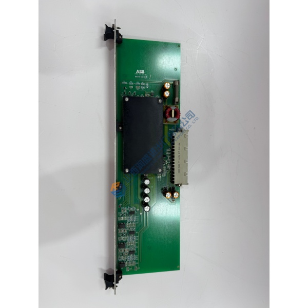
Installation & Configuration Guide
Phase 1 — Pre-Installation (est. 10 min)
De-energize the AC supply and DC bus. Wait 5 min for capacitor discharge. Tools: ESD wrist strap, multimeter (Fluke 115), torque wrench. Photograph existing wiring, mounting brackets and any parallel connections.
Phase 2 — Removal (est. 5 min)
Label every cable on the JZ connector. Release the mounting brackets or bolts. Lift the module clear of the cabinet floor or rack; inspect for capacitor swelling or connector damage.
Phase 3 — Installation (est. 10 min)
Apply ESD protection. Verify the part number DS2020DACAG2. Mount with the four brackets and bolts supplied for floor or rack installation. Connect the single 12-position JZ harness for AC input and DC output. When paralleling two modules, feed both from the same AC source. Complete the pre-power checklist.
Phase 4 — Power-On & Testing (est. 15 min)
Apply AC power and measure DC output voltage (nominal 126 V). Verify bus diode coupling and ride-through behavior if a battery is not present. Confirm stable operation under load for >30 min. Log the module replacement.
Troubleshooting quick-reference:
- No DC output → check AC input voltage, JZ connector seating and internal fuses
- Low voltage under load → verify parallel wiring and capacitor health
- Over-temperature → confirm free convection airflow and ambient limits