Description
Product Introduction
The GE DS303A2A01FXA010 heavy duty DC contactor switches field excitation circuits inside EX2100e generator regulator enclosures. Mounted on open panel surfaces, the device interrupts high-current direct currents without pulling destructive arcs. Bottom line — it works.
Integrating dedicated arc-extinguishing chutes across main contacts, the assembly quenches 50 A DC breaks reliably up to 600 V AC or 1,000 V DC. Running off a 24 V DC control signal, the coil actuation engages isolated auxiliary interlocks within milliseconds. Honestly, this rugged blowout structure is actually clever for preventing contact welding during emergency generator field tripping.
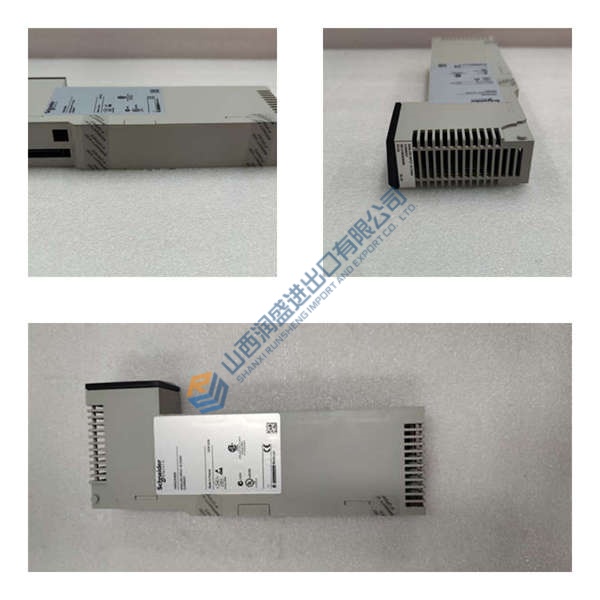
Pricing & Availability Note: Listed pricing serves as a reference only; actual unit cost depends on current warehouse stock and delivery urgency. Request a quick quote to check real-time pricing for the GE DS303A2A01FXA010.
Installation & Configuration Guide
Phase 1 — Pre-Installation (est. 10 min)
- Lock out and de-energize primary exciter power buses.
- Wait 5 minutes for busbar filter capacitors to bleed down safely.
- Gather socket wrenches, wire strippers, an ESD wrist strap, and a Fluke 115 multimeter.
- Export controller fault logs and photograph initial auxiliary contact stack configurations.
Phase 2 — Removal (est. 5 min)
- Unthread secondary control wires from coil screw terminals.
- Label high-current DC cables connected to main power lugs.
- Unbolt primary power cable lugs from the copper terminal studs.
- Remove four base mounting screws and carefully lift the 10 lbs contactor off the panel.
Phase 3 — Installation (est. 10 min)
- Put on a grounded ESD wrist band before handling low-voltage auxiliary contacts.
- Inspect the product nameplate to ensure the part number reads GE DS303A2A01FXA010.
- Replicate auxiliary interlock arrangements (NO versus NC alignment) from pre-removal photographs.
- Position the module onto panel mounting holes and tighten chassis hardware to 3.5 N·m.
- Connect main power cables to copper lugs, torquing terminal hardware to 8.0 N·m.
Phase 4 — Power-On & Testing (est. 15 min)
- Apply 24 V DC power to control coil circuits.
- Confirm mechanical plunger engagement occurs instantly with a crisp physical snap.
- Verify main contact continuity across power lugs using a multimeter in resistance mode.
- Check auxiliary contact state changes in the EX2100e diagnostic screen.
- Monitor contactor coil current for 30 minutes to confirm continuous holding stability.
Troubleshooting Quick-Reference
- Coil fails to pick up → Check 24 V DC control supply voltage; verify coil resistance across input screws.
- Severe contact arcing → Inspect arc chute placement; clear foreign debris from magnetic blowout channels.
- Auxiliary feedback fault → Verify plunger alignment; confirm interlock contact blocks seat completely into side slots.