Description
Product Introduction
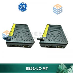
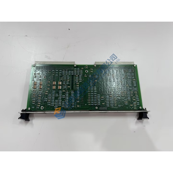
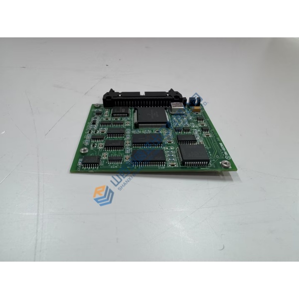
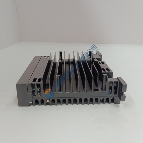
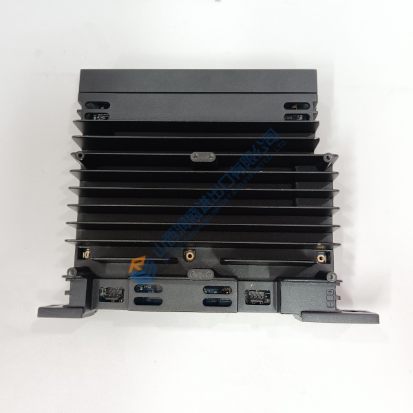
GE IS200EBRGH1A is the Exciter Bridge Interface Board (EBRG) used in the EX2100e excitation control system. It serves as the critical link between the digital control electronics and the power conversion bridge, handling SCR gate signals, thermal feedback, cooling signals and protective functions.
The board accepts thermal-sense and feedback inputs and issues SCR gate-drive outputs. It operates from 125 VDC supplied by the EDIS and is designed for one EBRG per Power Conversion Module (PCM). Compatible thyristor sizes include 42 mm, 52 mm and 77 mm. Conformal coating provides additional environmental protection.
Installation & Configuration Guide
Phase 1 — Pre-Installation (est. 10–15 min)
De-energize the excitation system and lock out all power sources including 125 VDC. Allow residual energy to dissipate. Tools: ESD wrist strap, multimeter (Fluke 115), torque tools. Photograph existing cabling, HSLA connections and board orientation.
Phase 2 — Removal (est. 10 min)
Label every connector (power, feedback, gate-drive, cooling and serial links). Disconnect cables carefully. Release the board from its mounting in the power conversion cabinet and remove.
Phase 3 — Installation (est. 15 min)
Verify the part number IS200EBRGH1A and conformal-coating markings. Seat the board firmly in the designated location. Reconnect all cables in the original order, ensuring proper seating of high-speed serial links and gate-drive wiring. Complete the pre-power interlock and continuity checks.
Phase 4 — Power-On & Testing (est. 20–30 min)
Apply 125 VDC control power first. Verify board status indicators and communication with the host controller. Perform a controlled excitation test under supervision, monitoring SCR firing, thermal feedback and cooling signals. Confirm stable operation and log the board replacement.
Troubleshooting quick-reference:
- No gate-drive output → check 125 VDC supply, HSLA link and enable signals
- Thermal or cooling faults → verify sensor inputs and fan/pump status
- Communication loss → inspect high-speed serial connections and grounding