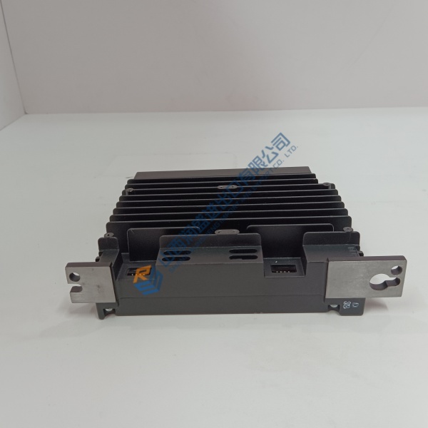
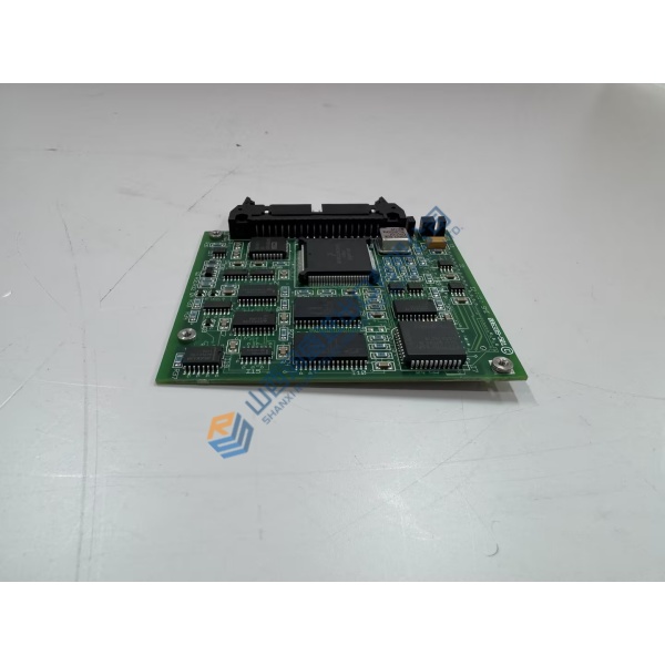
Description
Product Introduction
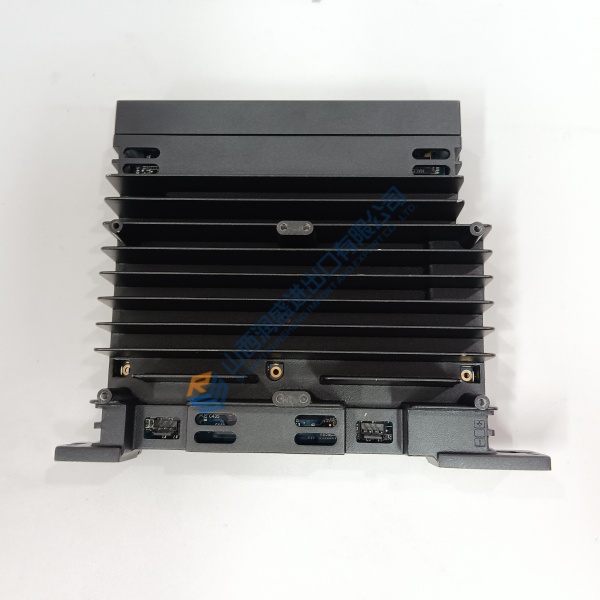
GE IS200SPIDG1A is the PROFIBUS Master Gateway Terminal Board (SPID) used in Mark VIe distributed control systems. It provides the mechanical mounting platform and electronic identification for the associated I/O pack (typically an IS220PPRF or equivalent PPRF pack).
The PROFIBUS connection is made through the DE-9 D-sub connector on the side of the I/O pack; the terminal board itself carries the electronic ID and power/interface connections. The design supports both simplex and hot-backup (redundant) configurations by using dual SPID boards with dual PPRF packs. Status LEDs on the I/O pack provide visual diagnostics.
Installation & Configuration Guide
Phase 1 — Pre-Installation (est. 10 min)
De-energize the Mark VIe cabinet and related field power. Tools: ESD wrist strap, multimeter (Fluke 115), torque tools. Photograph existing SPID location, PPRF seating and PROFIBUS cabling.
Phase 2 — Removal (est. 5–10 min)
Label the PROFIBUS cable and any Ethernet or power connections. Release the PPRF I/O pack from the SPID terminal board. Unbolt and remove the SPID board from its mounting bracket.
Phase 3 — Installation (est. 10–15 min)
Verify the part number IS200SPIDG1A. Mount the terminal board firmly using the designated brackets. Seat the PPRF I/O pack directly onto the SPID connector. For hot-backup systems, repeat with the second SPID and PPRF pair. Secure the packs using the threaded inserts next to the Ethernet ports. Connect the PROFIBUS cable to the DE-9 on the I/O pack.
Phase 4 — Power-On & Testing (est. 15–20 min)
Apply power and observe status LEDs on the I/O pack. Use ToolboxST to confirm electronic ID recognition, configure the PROFIBUS master parameters and verify network communication. Run a functional check of the associated I/O and log the replacement.
Troubleshooting quick-reference:
- I/O pack not recognized → check seating on SPID and electronic ID continuity
- PROFIBUS communication failure → verify DE-9 connection, termination and baud rate
- Dual configuration issues → confirm both SPID/PPRF pairs are powered and addressed correctly