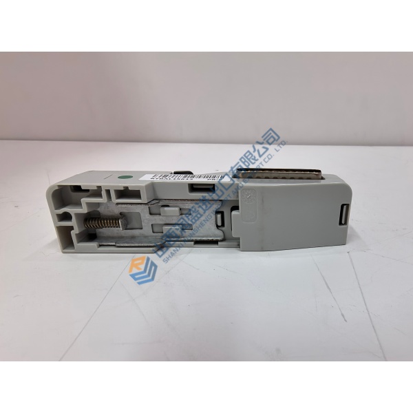
Description
Product Introduction
GE IS215UCVFH2AB is a UCV controller board for GE Mark VI Speedtronic turbine-control systems. It executes real-time application logic and exchanges data with turbine I/O hardware through the VME backplane.
Public supplier records identify the board as a dual-slot VME controller, but published technical details conflict on processor, memory, and architecture. Treat those values as unverified until the nameplate, board markings, and OEM documentation match your installed system.
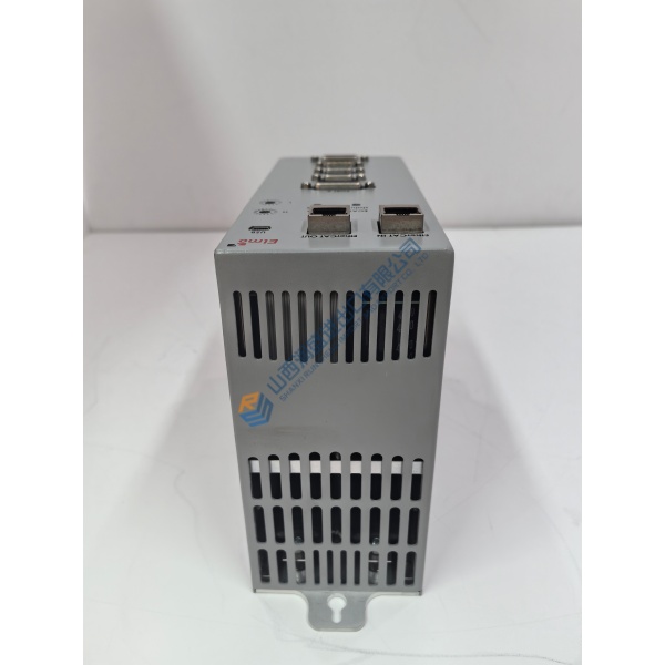
Do not copy unsupported processor, memory, temperature, or power figures into a purchase order. Several reseller pages attribute specifications to related UCV models or provide conflicting values. Confirm the exact IS215UCVFH2AB board revision and Mark VI system configuration before procurement.xydcontrol+1
The suffix matters. A nearby UCV model may use a different processor, memory arrangement, firmware image, connector configuration, or rack application. Do not substitute IS215UCVEH2AB, IS215UCVFH2A, or IS215UCVFH2B solely because the base UCV designation appears similar.
Installation & Configuration Guide
Phase 1—Pre-Installation — estimated 20 minutes
Place the turbine control system in the approved maintenance state. Follow the site switching procedure, isolate the controller rack as required, and wait at least 5 minutes for discharge before handling the board.
Prepare:
- ESD wrist strap and grounded ESD mat.
- Fluke 115 multimeter.
- Insulated screwdriver set.
- Board-extraction tool if specified by the VME rack.
- Mark VI configuration backup.
- Firmware and application-database records.
- Controller and rack drawings.
- Camera for board labels, switches, cables, and slot positions.
Export the application database, controller configuration, I/O assignments, network settings, alarm records, and diagnostic files. Record the original board serial number, revision, firmware, slot position, controller role, and neighboring board positions.
Photograph the front label, board connectors, front-panel indicators, rack layout, cable routing, and any jumpers or switches.
Phase 2—Removal — estimated 10 minutes
Label every cable before disconnecting it. Record connector locations and the identity of the corresponding VME slot.
Release the board retainers and pull the controller straight from the backplane. Avoid twisting the board. Inspect the VME connector pins for bending, oxidation, contamination, and heat damage.
Keep the removed board in anti-static packaging. Do not discard it until the replacement completes boot, communication, I/O, and application tests.