
Description
Product Introduction
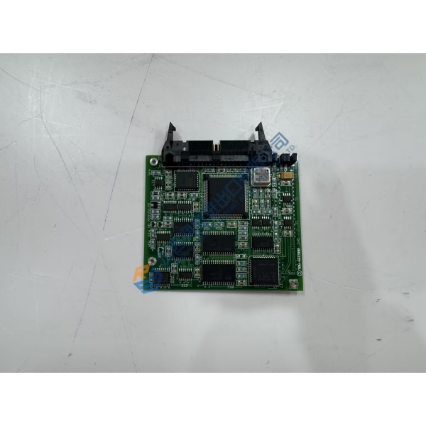
Intermittent communication faults or erroneous transducer readings on gas, steam, or wind turbine control systems often originate from aging interface boards experiencing thermal drift or degraded bus transceiver components. The General Electric IS215WETAH1C (109W6503P001) WETA board fixes these signal processing issues by providing stable, noise-isolated interface channels directly to the Mark VI control architecture.
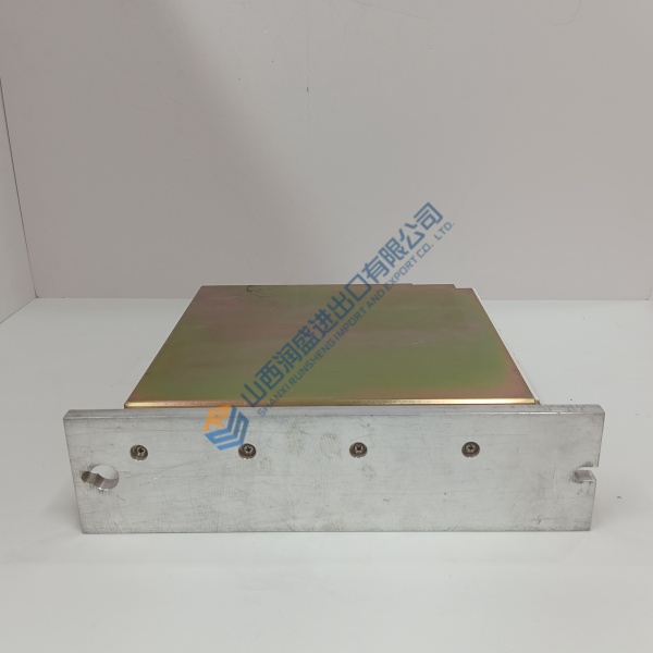
Engineered specifically for heavy-duty GE Speedtronic Mark VI racks, this printed circuit board handles high-speed field signal conditioning and processing without taxing the main system processor. In my experience, replacing a degraded WETA card stops spurious trip signals and restores precise monitoring across critical turbine control loops.
Installation & Configuration Guide
Phase 1 — Pre-Installation (est. 10 min): Power down the target Mark VI rack or confirm system redundancy permissions before performing card replacement. Wait 5 minutes for bus capacitors to discharge. Gather a torque driver, ESD wrist strap, and a digital multimeter. Photograph all ribbon cable routing, terminal board jumpers, and rack slot positioning before touching the old board.
Phase 2 — Removal (est. 5 min): Disconnect any front-faceplate cable connectors carefully by squeezing retaining latches. Loosen top and bottom captive retaining screws on the card faceplate, then ease the card ejector handles outward to unseat the board from the VME backplane. Slide the card straight out along its guide rails.
Phase 3 — Installation (est. 10 min): Fasten an ESD wrist strap to an unpainted chassis ground point before taking the new board out of its static bag. Verify the model label reads IS215WETAH1C / 109W6503P001. Align the card edges with the card guide tracks in the assigned rack slot, slide the board in smoothly until ejectors engage, and press handles flat to seat backplane connectors. Tighten retaining screws to 0.4 N·m.
Phase 4 — Power-On & Testing (est. 15 min): Restore power to the Mark VI rack and observe faceplate status LEDs during boot. Connect Toolbox / ToolboxST software to the Mark VI controller, verify card detection and firmware compatibility, and execute a signal diagnostic check. Run a 30-minute system health monitoring cycle to ensure zero communication errors on the VME backplane.
Troubleshooting Quick-Reference:
- DIAG / FAIL LED lit red → Reseat card in backplane; verify slot alignment and check backplane pin integrity.
- Toolbox software mismatch error → Check hardware revision level (H1C) against project configuration files.
- Signal noise on analog channels → Verify field cable shielding is terminated at designated terminal board ground bars.



