Description
Product Introduction
GE MMII-PD-1-2-240 is a digital motor protection and management relay engineered for low-voltage three-phase induction motors. The unit integrates current-based overload protection, process diagnostics, and motor control logic into a single panel-mounted enclosure for Motor Control Center (MCC) applications.
This relay incorporates a dedicated Profibus DP communication interface to send real-time current measurements, thermal capacity calculations, and alarm flags directly to central PLC networks. Its modular draw-out chassis allows rapid hardware swaps during planned system outages, lowering overall maintenance overhead.
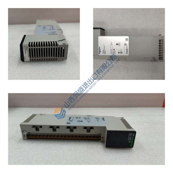
Frequently Asked Questions
Q: Are these units factory-new or surplus, and how do you test them? A: OEM production for this product series has ended, so available inventory is sourced from verified new surplus or decommissioned panels. Every GE MMII-PD-1-2-240 undergoes a strict 5-step SOP validation before dispatch:
- Inbound Inspection: Customs origin verification, anti-counterfeit serial checks, visual housing inspection, and terminal block mechanical verification.
- Live Functional Testing: Installed on a dedicated secondary injection test bench to verify 240 V AC power-up, Profibus DP communication handshakes, and current accuracy over a 24-hr run.
- Electrical Testing: Insulation resistance testing using a 500 V Megger (>10 MΩ target) and grounding continuity checks across panel chassis mounts.
- Hardware Verification: Recording installed firmware versions, backup relay logic configurations, and verifying DIP switch addressing.
- Final QC & Packaging: Sealed in anti-static shielding bags, cushioned with heavy bubble wrap, and labeled with a physical QC Passed tag.
Q: Can I hot-swap the GE MMII-PD-1-2-240 while the motor is running? A: No, you must never hot-swap this motor protection relay under active power. Unplugging CT current connections while energized creates dangerous open-circuit high voltages across CT terminals. Always isolate 240 V AC control power and open line breakers before pulling the unit from its mounting chassis.
Q: What technical pitfalls should field engineers avoid during replacement? A: In our field service experience, engineers encounter five critical mistakes during replacement:
- Current Transformer Secondary Rating: Verify that current input circuits match 1 A CT secondaries rather than 5 A CT inputs.
- Profibus DP Termination: Check that end-of-line bus termination resistors are enabled properly on the network segment.
- Control Power Voltage: Ensure the supply line matches 240 V AC; applying 120 V AC will result in power failure or intermittent resets.
- Relay Output Logic: Verify whether trip contact outputs are wired as Normally Open or Normally Closed before energizing control circuits.
- ESD Protection: Electrostatic discharge can compromise internal microprocessors. Always wear a grounded anti-static wrist strap during installation.