Description
Product Introduction
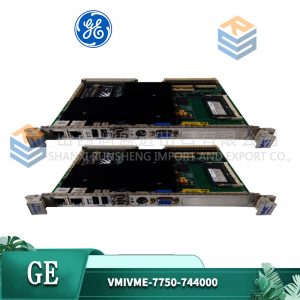
GE RS-FS-9001 provides critical speed processing and flame detection capabilities within GE Mark VIe control architectures. Designed for heavy-duty gas and steam turbines, this module condition-conditions raw frequency signals from magnetic pickups and flame detectors directly into the turbine control backplane. Operating on 24 V DC power loops, the unit processes high-speed pulse trains to execute overspeed protection algorithms in real time. In field deployments of AC800M systems, fast speed monitoring prevents catastrophic mechanical overspeed events.
Procuring legacy turbine control hardware during forced outages creates tremendous operational pressure. Dropping directly into standard Mark VIe VME rack slots, the module replaces aging speed cards without requiring field wiring harness changes. Is this design choice actually clever? Absolutely, because hardware-level frequency threshold detection operates independently of main processor scan cycles to trip the turbine safely. Listed pricing serves as reference only; actual market pricing depends on global inventory levels. Contact our procurement desk today to request an immediate price quote.

Quality Inspection and Verification SOP
In our testing facility, every incoming turbine control board undergoes rigorous multi-point verification before entering storage. We verify source documentation against OEM packing manifests and customs paperwork. Technicians perform anti-counterfeit inspections, examining serial numbers, PCB batch codes, and solder mask integrity. Physical checks ensure zero backplane pin bending, conformal coating flaking, or card edge oxidation.
Live functional testing begins by mounting the GE RS-FS-9001 into an energized Mark VIe test rack while monitoring power supply rails with a Fluke 115 multimeter. Observing startup LED behavior, we initiate communication handshakes across the rack backplane bus. Technicians inject high-frequency pulse trains using a precision signal generator, verifying pulse counting accuracy and overspeed trip contact state transitions during a 24-hour continuous load test. Insulation resistance is verified using a 500 V megohmmeter to ensure channel-to-ground isolation exceeds 10 MΩ. Firmware revisions are recorded, and hardware jumpers are photographed for customer records. Following final technician sign-off, the card is wrapped in anti-static shielding and boxed with high-density foam padding. Test photos and raw video recordings remain available on request. Units are confirmed functional after completing all tests above.
Technical Pitfall Guide for Integration Engineers
Having supported dozens of power station turnarounds, our engineering team highlights five critical mistakes that stall installations.
- Magnetic Pickup Air-Gap Misalignment: Setting MPU sensor tips too far from turbine ring gear teeth degrades signal amplitude, causing speed dropout alarms at low RPM. Set sensor air gaps precisely to manufacturer specification (typically 0.5 to 1.0 mm). Measure AC peak-to-peak voltage during slow-roll turning gear operation.
- Shield Grounding and Cable Noise Interference: Grounding speed signal cable shields at both ends creates ground loops that introduce false high-frequency pulse spikes. Ground cable shields at the control cabinet entry point only. Maintain physical separation between high-voltage motor leads and signal wiring. Photo. Photo. Photo.
- Firmware Revision and Jumpers Mismatch: Replacing speed processing modules without verifying hardware jumper settings causes pulse threshold detection failures. Replicate hardware jumper positions from original boards before slot installation. Specify target firmware versions during procurement.
- Incorrect Overspeed Trip Threshold Setup: Programming pulse-per-revolution (PPR) scaling parameters incorrectly in the control software triggers premature turbine trips on start-up. Calculate gear tooth counts and verify scaling factors in ControlST software before firing fuel burners.
- Electrostatic Discharge (ESD) Damage: Handling raw circuit boards without grounding accessories risks damaging sensitive CMOS pulse-shaping microchips — though your mileage may vary depending on ambient humidity. I watched an engineer skip the strap in January. The module smoked on power-up. $2,000 gone. Always wear an ESD wrist strap connected to chassis ground.
Keep these five points in mind and you’ll cut 90% of your rework time.
Installation & Configuration Guide
Phase 1 — Pre-Installation (Estimated Time: 10 minutes)
De-energize main control rack power supplies and lock out 24 V DC circuit breakers. Wait 5 minutes for internal capacitors to discharge completely. Gather a 3 mm slotted screwdriver, ESD grounding strap, and frequency generator. Export system parameters and MPU scaling files from ControlST engineering software. Photograph original card slot positioning, wiring harnesses, and hardware jumper settings.
Phase 2 — Removal (Estimated Time: 5 minutes)
Tag every terminal block connector and signal cable before detachment. Loosen top and bottom board retaining screws on the front panel frame. Unlatch ejector handles and pull the module straight out perpendicular to the VME backplane frame. Inspect backplane receptacle slots for dust or bent connector pins.
Phase 3 — Installation (Estimated Time: 10 minutes)
Put on a grounded anti-static wrist strap before opening the protective ESD packaging of the GE RS-FS-9001. Replicate jumper settings matching your pre-installation reference photos. Align card edges with subrack guide rails and slide the module inward until backplane connectors seat firmly. Tighten top and bottom retaining screws to 0.4 N·m. Reattach terminal wiring blocks to designated front panel ports.