Description
Product Introduction
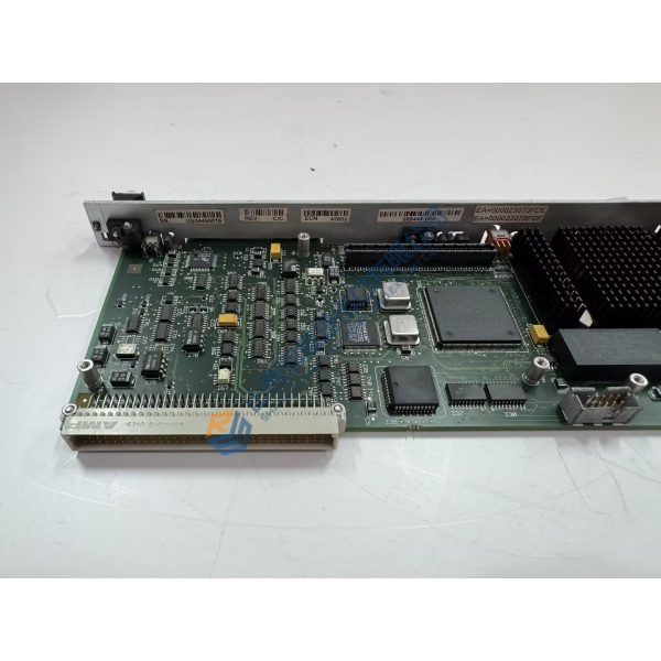
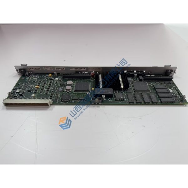
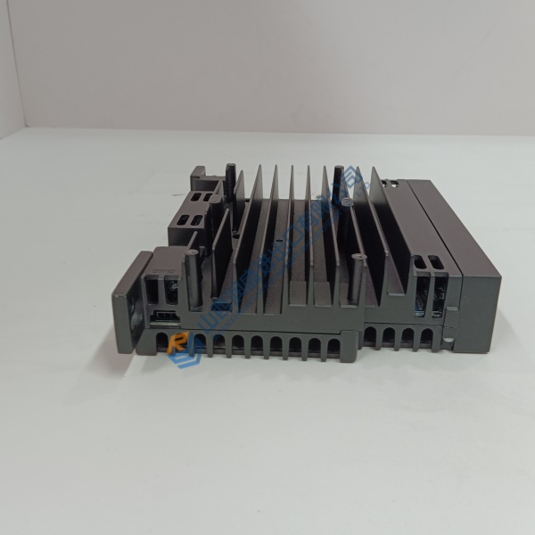
Unexpected shutdowns, voltage fluctuations, or control board failures in heavy industrial UPS systems threaten critical continuous processes in oil & gas, power generation, and chemical facilities. The GUTOR 0P0284AC industrial power module resolves these mission-critical vulnerabilities by restoring stable power management, precise signal regulation, and robust system diagnostics inside GUTOR PEW/PDW series UPS units.
Manufactured specifically for harsh power environments, this genuine GUTOR board features heavy-duty electronic components designed for continuous 24/7 operation. In my experience, replacing an aging or faulted 0P0284AC module eliminates nuisance inverter/rectifier fault alarms and stabilizes output regulation under high-surge dynamic loads.
Installation & Configuration Guide
Phase 1 — Pre-Installation (est. 10 min): Isolate main AC supply, bypass AC input, and DC battery isolation breakers feeding the GUTOR UPS cabinet. Follow strict safety lockout/tagout (LOTO) procedures. Wait at least 15 minutes for high-voltage DC bus capacitors to fully discharge. Use a calibrated multimeter to verify zero voltage across main bus bars. Gather anti-static tools, insulated screwdrivers, and an ESD wrist strap. Photograph all cable harnesses, jumper positions, and connector locations before removing the old module.
Phase 2 — Removal (est. 5 min): Put on an ESD grounding wrist strap. Carefully disconnect all ribbon cables, power wiring, and terminal plugs connected to the 0P0284AC board. Unscrew the retention standoffs or mounting screws holding the PCB to the internal rack frame, and carefully lift the module out. Inspect mounting standoffs for debris or mechanical damage.
Phase 3 — Installation (est. 10 min): Verify that DIP switches or jumper pin settings on the new 0P0284AC match the original board configuration exactly. Position the board onto the mounting standoffs and secure retention screws evenly to ~1.0 N·m torque. Reattach all wiring harnesses and ribbon connectors according to your pre-removal photographs, ensuring locking tabs click firmly into place.
Phase 4 — Power-On & Testing (est. 15 min): Close the control power fuses and apply auxiliary control voltage. Observe onboard diagnostic LEDs and verify normal boot sequences on the GUTOR front display panel. Perform a DC bus voltage check and execute a simulated mains-to-battery transfer test under light load to confirm switching synchronization and fault-free operation.
Troubleshooting Quick-Reference:
- Control Power LED OFF → Inspect incoming DC/AC auxiliary supply fuses and verify connector pin seating.
- System Inverter Fault Alarm → Check jumper settings on 0P0284AC; confirm ribbon cable ribbon shields are grounded.
- Voltage Regulation Drift → Recalibrate system parameters via GUTOR service interface software if required.
FAQ
Can I just drop this in and go? In most replacement scenarios, yes—provided the jumper and DIP switch settings match your existing board configuration. However, depending on the UPS firmware revision, you may need to perform a zero-point voltage/current calibration via the GUTOR service interface.
Is GUTOR part of Schneider Electric? Yes. GUTOR Electronic LLC is a specialized Swiss manufacturer of custom industrial UPS systems and operates as a high-reliability industrial brand under Schneider Electric.