Description
Product Introduction
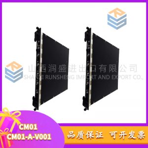
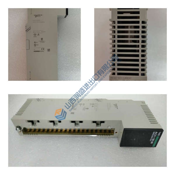
The Honeywell EG1033AC01 is a UV flame amplifier from the EG (LG) series, designed for combustion safety monitoring in industrial gas turbines, boilers, and burner systems. It drives and monitors two LG1093-series UV sensors (Geiger-Mueller phototubes) that detect ultraviolet radiation from hydrocarbon flames in the 185–265 nm (solar-blind) spectrum.
This module stands out for its dual-channel architecture—each amplifier can power two sensors independently and provide separate relay outputs for flame present/loss signals. In field deployments of GE Mark VI/VIe turbine systems, we’ve seen flame detection times consistently under 0.1 s with proper 28–35 V DC supply and shielded coaxial cabling. The 35+ year track record on GE and licensee turbines (LM2500, LM6000, Frame 5/6/7/9) makes it a proven choice for power generation, pumping stations, and marine applications where flameout protection is non-negotiable.
Installation & Configuration Guide
Phase 1—Pre-Installation (est. 10 min)
De-energize the 28 V DC supply and wait 5 min for capacitor discharge. Grab a Torx T20, wire strippers, and a Fluke 115 multimeter. Export your current turbine configuration and photograph the existing amplifier’s terminal wiring, sensor connections, and rack position.
Phase 2—Removal (est. 5 min)
Label every sensor cable before disconnecting—Channel A/B, Sensor 1/2. Release the 4-hole flange bolts, pull the module straight out, and inspect the backplane connector pins for bent contacts or corrosion.
Phase 3—Installation (est. 10 min)
Strap on your ESD wristband. Verify the part number matches EG1033AC01. Replicate the terminal block wiring from your photos—28 V DC polarity, relay outputs, shield ground. Seat the unit on the flange, torque M4 bolts to ~1.5 N·m, reconnect the coaxial sensor cables, then run a pre-power checklist: backplane continuity, 28 V DC supply polarity, ground bond.
Phase 4—Power-On & Testing (est. 15 min)
Verify supply voltage is 28 V DC (±10%). Power up and watch the LEDs: green = RUN, red flash = ERR, amber flash = DIAG. Hook up your DCS or turbine control system, confirm relay outputs for flame present/loss, then run a full I/O loop test. Log at least 30 min of stable operation before signing off.
Troubleshooting quick-reference:
- No comms → check 28 V DC, coaxial cable, sensor bias voltage (350 V DC)
- ERR steady → sensor fault (check for open circuit or short)
- Download fails → verify cable and software version
- Over-temperature → check 100 mm clearance above/below, 30 mm sides