Description
Product Introduction
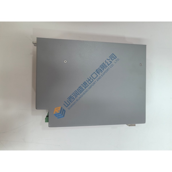
Honeywell S0762960 is a 762 VITO interface unit MRT printed circuit board for Enraf tank temperature measurement equipment. It connects the MRT probe assembly to the associated gauging electronics in petroleum storage and process applications.
For buyers sourcing a 762 VITO interface PCB, the main procurement risk is part-number confusion. Listings also show related S0762950 and S0762970 boards, so confirm the installed board marking and MRT configuration before ordering. Public listings commonly show quote-only or out-of-stock status.pmintegrators+1
The 762 VITO system uses multi-point Pt100 temperature measurement. Public 762 documentation describes 4–14 temperature elements, 0.01 °C resolution, and a standard product-temperature range of −50 to +120 °C; those figures apply to the system or probe documentation, not automatically to the S0762960 PCB. Verify with the OEM datasheet before publishing them as board specifications.
Installation & Configuration Guide
Phase 1—Pre-Installation — Estimated 10 minutes
De-energize the cabinet and wait at least 5 minutes for discharge. Confirm the work permit, area classification, and intrinsic-safety requirements before opening the equipment.
Prepare a calibrated multimeter, insulated hand tools, ESD wrist strap, ESD mat, labels, camera, and the approved wiring documentation. We use a Fluke 115 multimeter for voltage, continuity, and basic electrical checks.
Export the existing configuration where the 762 system permits it. Photograph the PCB, terminal wiring, board labels, DIP switches, jumpers, rack position, and cable routing. Record the original firmware or board revision before removal.
Phase 2—Removal — Estimated 5 minutes
- Label every wire before disconnecting it.
- Confirm zero voltage at the relevant terminals.
- Release the DIN rail latch or board retaining hardware, where fitted.
- Pull the PCB perpendicular to the backplane.
- Inspect backplane connector pins for bending, oxidation, contamination, or recessed contacts.
- Place the removed board in an ESD-safe bag.
Phase 3—Installation — Estimated 10 minutes
Start with ESD protection. Confirm the replacement marking reads S0762960 and matches the removed board’s MRT application.
Replicate every DIP-switch and jumper position from the photographs. Seat the board until the retaining latch engages. Reconnect labeled wiring and tighten terminals to approximately 0.5 N·m only when the terminal manufacturer’s specification supports that value.