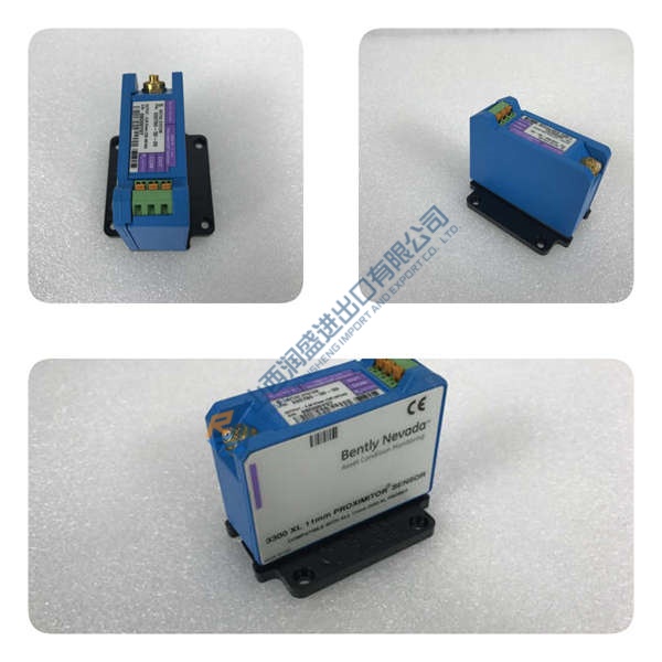
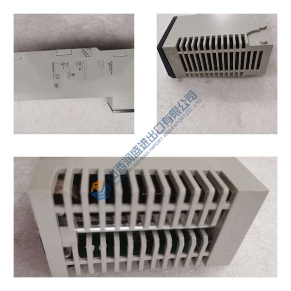
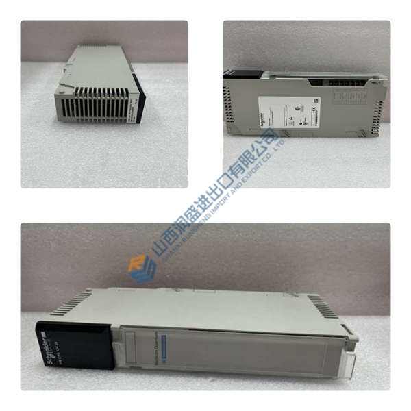
Description
Product Introduction
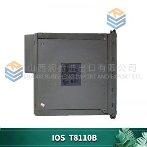
ICS Triplex T8293 is a high-density, fault-tolerant analogue input module engineered for Rockwell Automation Trusted TMR safety instrumented systems. Designed specifically for critical safety applications—including Emergency Shutdown (ESD), Fire and Gas (F&G) detection, and Burner Management Systems (BMS)—this card interfaces field transmitters (measuring pressure, temperature, flow, or level) directly to the main TMR processor. Featuring 40 isolated channels with hardware-level majority voting, it processes 4–20 mA current loop signals with high accuracy and onboard line diagnostic capabilities. In field deployments of AC800M systems, reliable analogue channel monitoring prevents false safety trips and unannounced process shutdowns.
Procuring legacy safety I/O modules during forced plant turnarounds creates extreme operational pressure. Designed for live insertion directly into standard Trusted I/O companion slots, the module replaces faulty analogue input cards without requiring system downtime or field wiring modifications. Is this design choice actually clever? Absolutely, because triple redundant A/D converters perform hardware voting on every sample to eliminate single-point measurement drift or conversion errors. Listed pricing serves as reference only; actual market pricing depends on global inventory levels. Contact our procurement desk today to request an immediate price quote.
Quality Inspection and Verification SOP
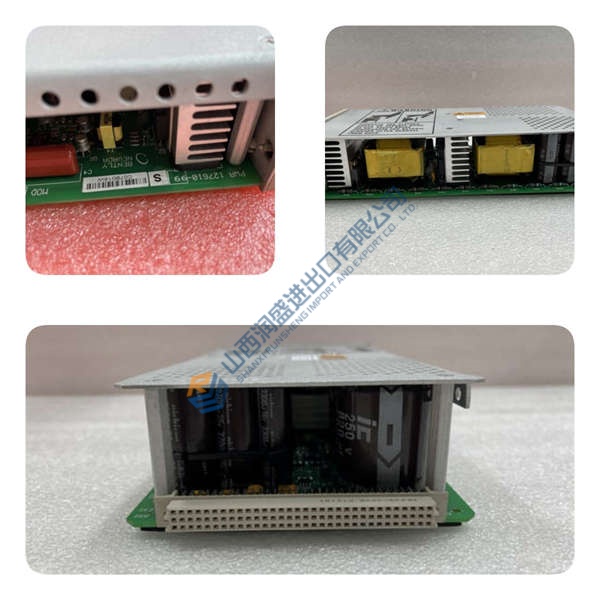
In our testing facility, every incoming TMR analogue input module undergoes rigorous multi-point verification before entering storage. We verify source documentation against OEM packing manifests and customs paperwork. Technicians perform anti-counterfeit inspections, examining serial numbers, PCB batch codes, and conformal coating uniformity. Physical checks ensure zero backplane pin bending, connector housing fractures, or card edge oxidation.
Live functional testing begins by mounting the ICS Triplex T8293 into an energized Trusted TMR test chassis while monitoring internal bus voltages with a Fluke 115 multimeter. Observing startup LED diagnostics, we initiate communication handshakes across the backplane to the Workbench engineering station. Technicians inject precision 4.0 mA, 12.0 mA, and 20.0 mA current loop signals using a process calibrator across all 40 channels, verifying signal voting, out-of-range alarms, and line-fault triggers during a 24-hour continuous load test. Isolation resistance is verified using a 500 V megohmmeter to ensure channel-to-ground isolation exceeds 10 MΩ. Firmware revisions are recorded, and address jumpers/switches are photographed for customer records. Following final technician sign-off, the module is wrapped in anti-static shielding and boxed with high-density foam padding. Test photos and raw video recordings remain available on request. Units are confirmed functional after completing all tests above.