
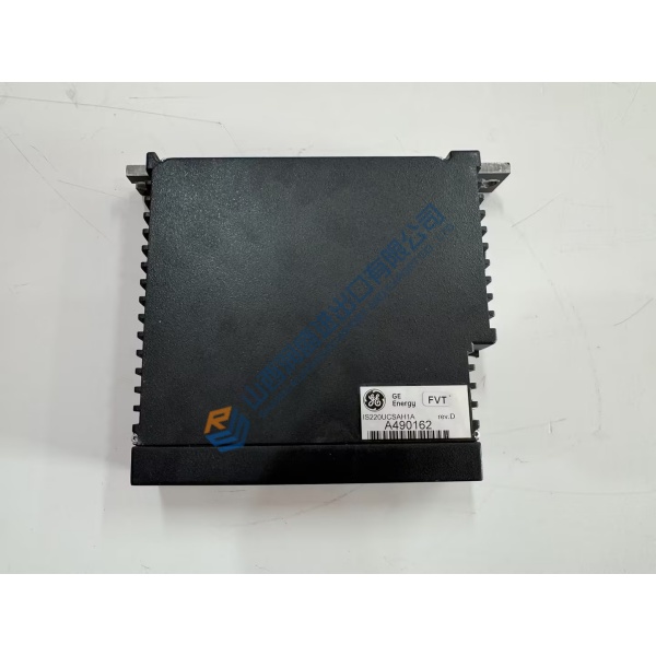
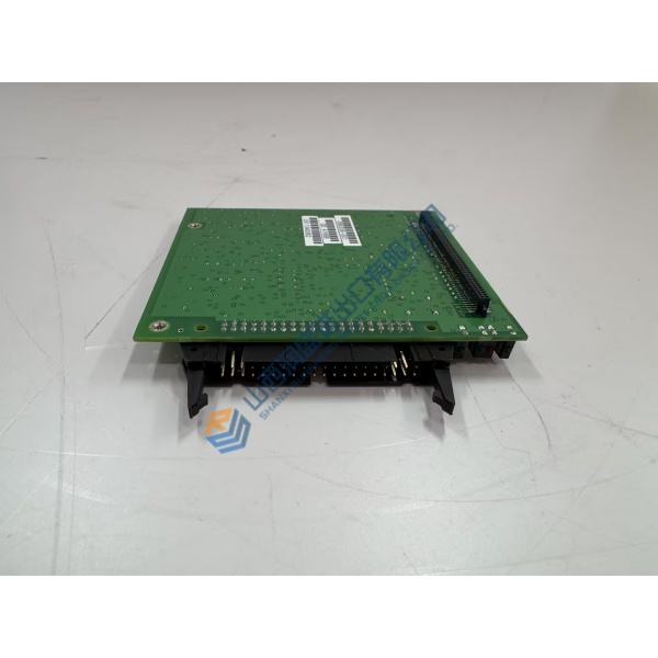
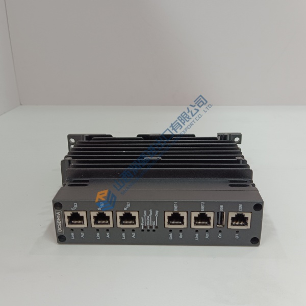
Description
Product Introduction
High-performance packaging lines often stall due to erratic motor feedback or sudden winding failure. The KEB A3.SM.000-62DY synchronous servo motor resolves these machine downtime issues by maintaining tight speed stability across high-duty dynamic cycles.
Featuring neodymium permanent magnets and integrated resolver feedback, this motor holds steady positional accuracy even under rapid directional changes. In my experience, replacing an aging unit with this motor drops thermal losses significantly and maintains operational continuity on high-speed feed axes.
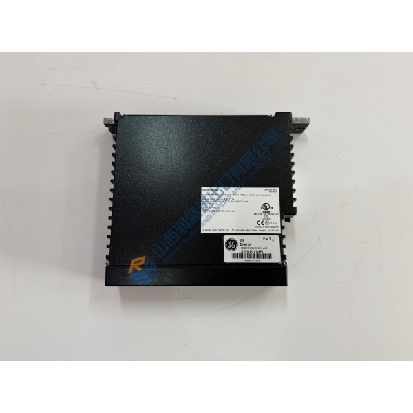
Installation & Configuration Guide
Phase 1 — Pre-Installation (est. 10 min): Power down the drive amplifier and wait 5 minutes for bus capacitors to discharge. Gather a torque wrench, metric hex keys, and a insulation multimeter. Photograph the original cable routing, shaft alignment setup, and terminal pinouts before removing anything.
Phase 2 — Removal (est. 5 min): Unplug power and feedback cables carefully—do not pull by the wiring harness. Loosen the mounting bolts on the motor flange, then slide the unit straight out to avoid damaging the coupling or keyway. Inspect the mating gearhead or coupling for mechanical wear.
Phase 3 — Installation (est. 10 min): Put on your ESD wrist strap first. Verify the part number on the nameplate matches the schematic. Replicate mechanical alignment, checking radial runout before tightening flange bolts to 5.5 N·m. Connect power and resolver cables until connectors lock in place.
Phase 4 — Power-On & Testing (est. 15 min): Measure incoming power line voltage to confirm 400 V AC supply limits. Apply 24 V DC logic power to the inverter and observe status LEDs (green indicates READY). Run a slow point-to-point test via drive commissioning software, checking motor direction and encoder feedback. Run a 30-minute burn-in cycle while checking housing temperature rise.
Troubleshooting Quick-Reference:
- No feedback signal → Check resolver connector seating and cable shield grounding.
- Motor vibrates violently on enable → Swap resolver phase wiring or recalibrate commutation offset angle.
- Over-temperature fault → Verify cooling airflow around housing; inspect mechanical load for binding.



