
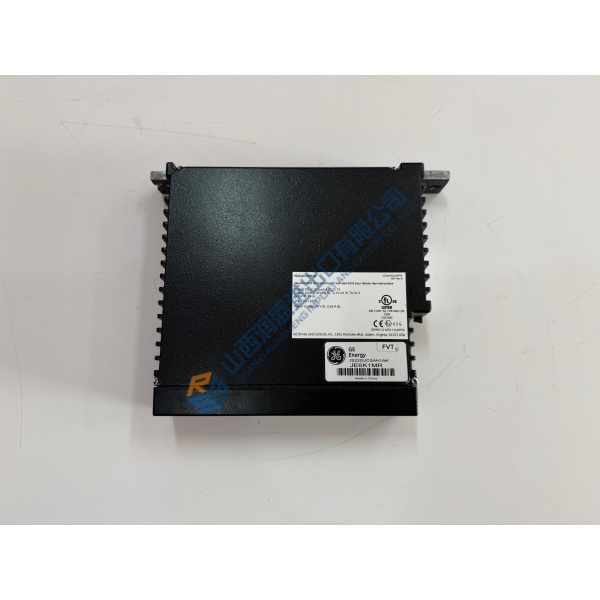
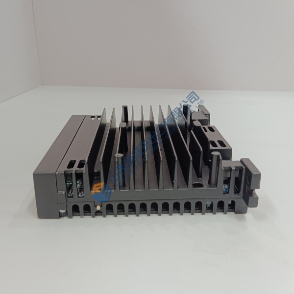
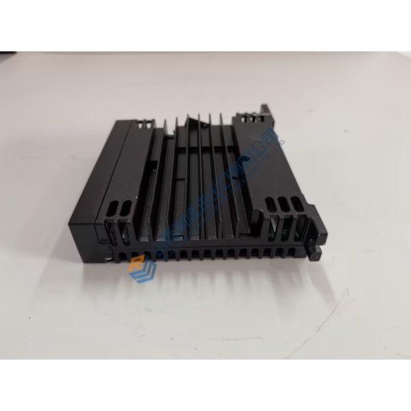
Description
Product Introduction
Unexpected inverter overcurrent faults or internal power stage failures on automated production lines bring output to an immediate stop. The KEB CDB32.004,C3.7 frequency inverter resolves these nuisance trips by providing tight current vector regulation across high-duty processing cycles.
Built with high-efficiency IGBT power modules and robust bus filtering, this drive maintains precise motor speed control even under fluctuating mechanical loads. In my experience, dropping this drive into a machine panel eliminates nuisance thermal shutdowns and stabilizes speed control on dynamic material handling axes.
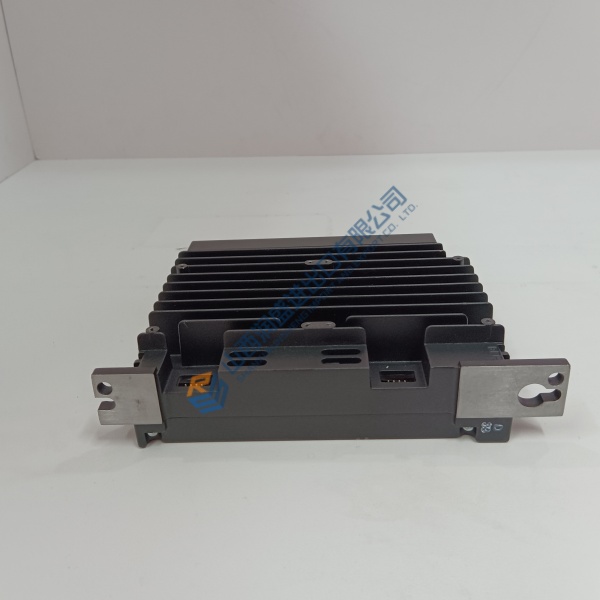
Installation & Configuration Guide
Phase 1 — Pre-Installation (est. 10 min): Disconnect all incoming mains power to the cabinet and wait 5 minutes for the DC bus capacitors to fully discharge. Use a digital multimeter to confirm zero volts across terminals ++ and — before proceeding. Photograph terminal block wiring, shield ground bonds, and parameter display keypad settings before pulling the old drive.
Phase 2 — Removal (est. 5 min): Unbolt field wiring terminals for mains power, motor leads, and dynamic braking resistors. Loosen the four mounting screws securing the heatsink frame to the enclosure backplate, then lift the drive straight off the panel. Inspect the mounting panel surface for dirt, debris, or thermal grease buildup.
Phase 3 — Installation (est. 10 min): Strap on an ESD grounding band before handling control electronics. Verify the part number on the side chassis label matches your engineering BOM. Bolt the drive securely to the backplate to ensure proper heatsink heat transfer, tightening screws to 2.5 N·m. Reconnect power and motor wiring (~1.2 N·m torque), ensuring 360-degree shield grounding clamps are secured on all motor leads.
Phase 4 — Power-On & Testing (est. 15 min): Measure line voltage to confirm 400 V AC supply stability. Apply control power and observe the keypad display (no fault codes displayed). Upload parameters using KEB COMBIVIS software or manually program motor plate values into the parameter menu. Run a low-speed jog test to confirm correct motor shaft rotation, then run a 30-minute full-load operational cycle while logging drive temperature.
Troubleshooting Quick-Reference:
- E.OP fault (Overvoltage) → Check braking resistor connections or increase deceleration time.
- E.OC fault (Overcurrent) → Inspect motor winding insulation and verify acceleration ramp times.
- Keypad remains blank → Check incoming 24 V DC auxiliary power or test internal line fuses.



