Description
Product Introduction
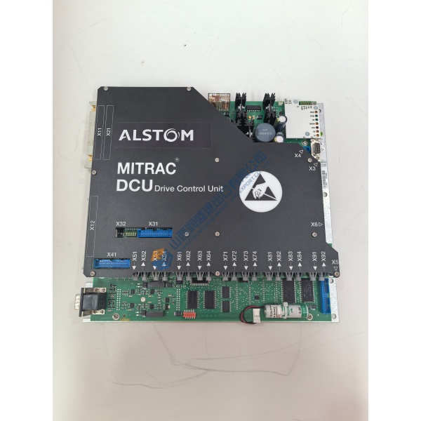
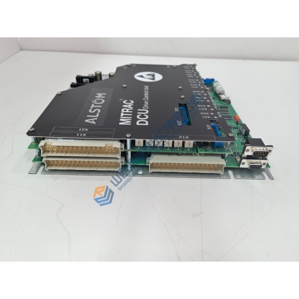
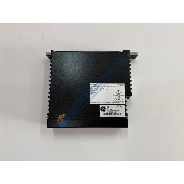
A controller board failure inside an RF match network or gas box stops etch processes immediately, risking costly production delays. The LAM 685-069171-100 provides reliable signal conditioning and real-time power control for high-vacuum semiconductor fabrication equipment. Built for high-reliability cleanroom environments, it mounts directly into Lam Research tool backplanes without requiring frame or harness modifications.
In field deployments across Lam Research Alliance, Kiyo, and Vector processing systems, this module maintains sub-millisecond response loops for plasma density and impedance tuning. The LAM 685-069171-100 integrates into tool control networks to keep wafer processing lines running smoothly. Listed prices serve as a baseline market reference; actual costs depend on global surplus availability and current lead times. Contact our procurement team directly to request an exact quote.
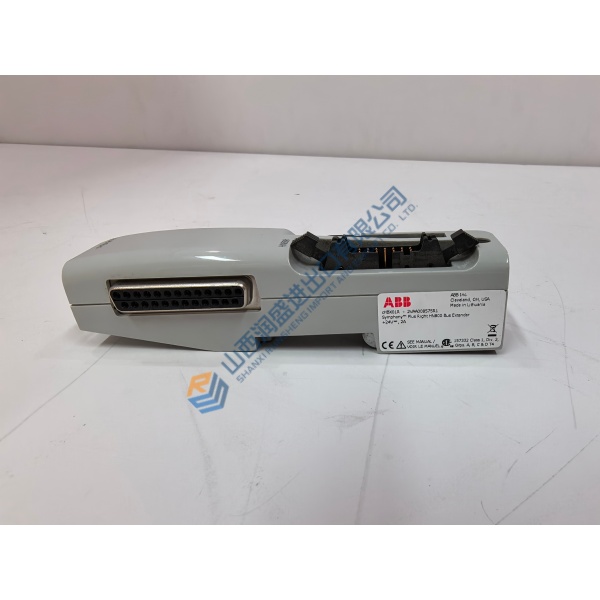
Installation & Configuration Guide
Phase 1 — Pre-Installation (est. 10 min)
De-energize main tool rack power feeds and lock out RF generators. Wait 5 minutes for power supply decoupling capacitors and match network circuitry to fully discharge. Assemble a metric hex driver set, torque driver, anti-static wrist strap, and digital multimeter. Export tool diagnostic logs and vacuum system configuration files via the main GUI. Take clear photos of all backplane ribbon cables, ground straps, and card slot alignments on the active LAM 685-069171-100 module.
Phase 2 — Removal (est. 5 min)
Label every interface connector and fiber jumper with port tags before disconnecting them. Loosen the top and bottom captive thumbscrews on the module front panel. Disengage the card ejector levers by pulling them outward simultaneously. Gently slide the board out of the rack guide channels along its card tracks. Inspect the backplane connector pins inside the chassis for bent contacts or thermal discoloration.
Phase 3 — Installation (est. 10 min)
Put on your ESD wrist strap and bond its grounding lead to the tool frame chassis. Remove the replacement LAM 685-069171-100 from its anti-static packaging. Verify the complete part number and revision suffix on the board label against your work order. Align the card edges with the card cage guide rails, pushing the unit steadily inward until the ejector levers contact the frame lip. Seat the board firmly into the backplane connector by pressing the levers flush, then tighten the captive panel screws to ~0.6 N·m. Reconnect external cable harnesses.
Phase 4 — Power-On & Testing (est. 15 min)
Measure incoming voltage at the chassis test points — verify 24 V DC nominal before re-energizing main control breakers. Turn on power. Observe the diagnostic LEDs during initialization: Power status illuminates steady green, Fault indicators clear after self-check, and communication link LEDs show active packet flow. Access tool diagnostic software to run a hardware handshake and zero-calibrate RF match stepper motor/capacitor feedback loops. Monitor telemetry for 30 minutes before resuming process runs. Log the replacement details in your fab maintenance log.
Quick Troubleshooting Reference
- Fault LED On (Red / Amber): Backplane power rail dip, match motor limit trip, or sensor signal loss; verify input DC voltage and wiring harnesses.
- No Communication / Tool Read Error: Reseat board in chassis to clear backplane pin resistance; check node address switch or jumper settings.
- RF Match Hunting / Instability: Recalibrate sensor offset values in software; verify low-resistance chassis ground bonding.