Description
Product Introduction
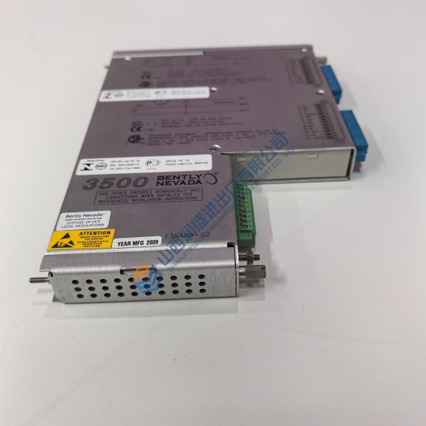
The MOOG D664-4758 is a two-stage servo proportional valve from the D664 series. It mounts to ISO 4401 Size 08 (NG25) manifolds and drives hydraulic actuators in metal forming, turbine control, and test stand applications.
What sets this valve apart is the ServoJet pilot stage — a high-flow design that resists contamination better than older jet-pipe designs. The main stage uses LVDT position feedback for closed-loop spool control. At 210 bar pilot pressure, the valve achieves 0 to 100% stroke response in approximately 48 ms.
Installation & Configuration Guide
Phase 1 — Pre-Installation (est. 10 min)
De-energize the hydraulic power unit and control cabinet. Verify zero pressure at the valve manifold with a calibrated gauge. Photograph the valve’s electrical connector wiring and record the full model code from the nameplate. D664-4758 suffixes differ in spool type, rated signal, and fail-safe option.
Phase 2 — Removal (est. 5 min)
Label hydraulic lines P, T, A, B before disconnecting. Tag the electrical connector. Loosen mounting bolts in a cross pattern. Inspect the manifold surface for scratches or corrosion — any imperfection over 0.01 mm across 100 mm will cause leakage. Cap all ports immediately.
Phase 3 — Installation (est. 10 min)
Confirm the replacement nameplate matches D664-4758 and the spool code matches your original. Install new O-rings (NBR 85 Shore or FPM as required). Seat the valve on the manifold and torque mounting bolts evenly. Reconnect electrical per photos. Verify pilot connections X and Y if external.
Phase 4 — Power-On & Testing (est. 15 min)
Energize 24 V DC supply. Confirm the valve’s integrated electronics power up without fault. Command a small step signal (e.g., 10% of rated) and observe actuator movement. Check for external leakage. Run a full 0–100% step and verify response. Log the swap with valve serial number and date.
Troubleshooting Quick-Reference:
- No actuator movement → check enable signal, power supply, cable continuity
- Slow or erratic response → check hydraulic fluid cleanliness (ISO 4406 <14/11 recommended); contaminated fluid is the leading cause of valve degradation
- External leakage at mounting face → inspect manifold flatness and O-ring condition
- ❗ Pilot connection mismatch → D664 valves ship with either X/Y internal or external pilot configuration. Using the wrong setup can lock the valve or create uncontrolled movement. Verify against the full model code before installation.