Description
Product Introduction
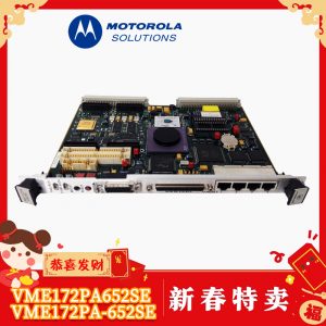
Processing bottlenecks, memory errors, or backplane timeout faults in legacy VME control racks can halt critical radar, simulation, or industrial automation systems. The Motorola / Emerson MVME7100 VMEbus Single Board Computer addresses performance demands and system obsolescence by introducing high-performance dual-core PowerPC processing directly into 6U VME64x backplane environments.
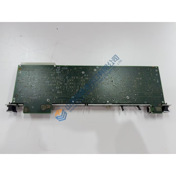
Engineered for high-reliability military, defense, and industrial control systems, the MVME7100 features a Freescale MPC8641D processor, dual PMC-X/XMC expansion slots, and Gigabit Ethernet channels. In my experience, upgrading aging single-core VME boards to the MVME7100 provides the computational throughput needed for high-speed data acquisition loops without requiring a complete rack overhaul.
Installation & Configuration Guide
Phase 1 — Pre-Installation (est. 10 min): Fully isolate power to the VME chassis and follow ESD lockout procedures. Gather an ESD wrist strap, board extraction tools, flathead screwdriver, and a digital multimeter. Photograph all onboard jumper settings, DIP switches, PMC mezzanine card locations, and backplane cabling before removing the existing board.
Phase 2 — Removal (est. 5 min): Unplug front-panel Ethernet, serial, and PMC I/O cabling. Unlock the top and bottom VME ejector handles by pressing the release tabs and pulling the handles outward simultaneously. Slide the SBC smooth out of the chassis card guides. Inspect backplane connector pins for bends or oxidation.
Phase 3 — Installation (est. 10 min): Wear an ESD wrist strap connected to a verified chassis ground. Inspect the replacement board label to confirm the model reads MVME7100. Transfer any required PMC/XMC expansion modules from the old board to the new MVME7100, securing standoff screws to 0.4 N·m. Align card edges with the card guide tracks, slide the board in smoothly until ejector handles engage backplane connectors, and press handles flat to lock the board in place.
Phase 4 — Power-On & Testing (est. 15 min): Apply chassis power and observe front-panel LEDs during system boot (green RUN LED steady, diagnostic LEDs clearing). Establish a serial console connection (115200 baud default) to access MOTLoad firmware or VxWorks/Linux bootloader prompt. Run onboard MOTLoad diagnostic suites to verify RAM, VME interface, and network links before loading operating system kernels.
Troubleshooting Quick-Reference:
- FAIL LED illuminated red → Verify VME chassis +5V / +3.3V power rails with a multimeter; check DIP switch boot configurations.
- No serial console output → Check serial null-modem pinout settings and baud rate matching (default 115200 8-N-1).
- VME backplane bus error → Confirm TSI148 VME bridge settings match backplane slot addressing and system controller configuration.