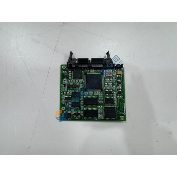
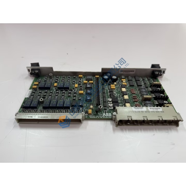
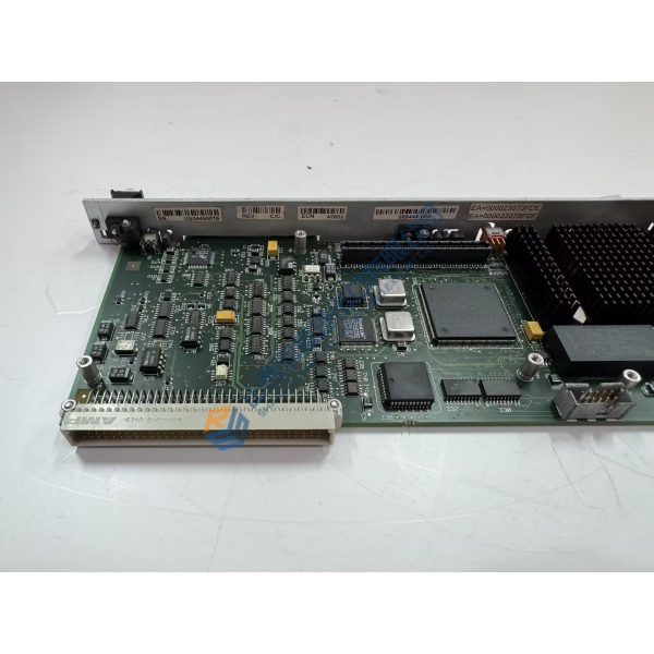
Description
Product Introduction
Gate-driver pulse jitter and signal attenuation inside medium-voltage power stacks frequently trigger nuisance overcurrent trips or phase imbalances. The PC000506245 (MVDL1000‑4701) GE medium voltage drive control board fixes power-bridge switching errors by providing precise, fiber-optically isolated gate firing pulses across liquid-cooled MV7000 converter bridges. Designed for high-demand applications including marine propulsion, rolling mills, and large utility pumping stations, this card maintains tight switching synchronization under severe load fluctuations.
Field operation logs across heavy manufacturing facilities confirm that replacing a degraded power interface card eliminates false gate-fault alarms and restores clean phase balancing. Swapping out aged firing circuitry protects high-power IGBT/IGCT modules from costly commutation failures and unexpected shutdown sequences. Honestly, running worn gate control boards in high-voltage drive stacks is an expensive risk that leads to unplanned downtime. This unit ships pre-tested from surplus warehouse stock, enabling engineering teams to clear drive fault codes before scheduled plant restarts.
Key Technical Specifications
- Parameter: Value
- Assembly Part Number: PC000506245
- Board Hardware Reference: MVDL1000‑4701
- Manufacturer: GE Power Conversion (formerly Converteam)
- System Family: MV7000 Liquid-Cooled MV Drive Systems
- Module Type: Gate Driver & Power Interface Board
- Voltage Class: 1000V nominal rating
- Auxiliary Power: 24V DC (18 to 30V DC operational range)
- Signal Interfaces: Fiber-optic transmitters and receivers for isolated gate control
- Cooling Integration: Optimized for liquid-cooled heat-sink phase assemblies
- Operating Temperature: −10 to +60 °C (14 to 140 °F)
- Conformal Coating: Heavy-duty industrial environmental protection standard
Installation & Configuration Guide
Phase 1 — Pre-Installation (est. 10 min) De-energize the main medium-voltage supply breaker and auxiliary control power feeds. Allow a minimum of 15 to 20 minutes for high-voltage DC bus capacitors to discharge safely below 50V DC. Verify zero voltage using an appropriately rated high-voltage meter. Attach an ESD grounding wrist strap. Photograph all fiber-optic cable paths, wiring looms, and onboard DIP switch/jumper positions before touching the original board.
Phase 2 — Removal (est. 5 min) Disconnect all fiber-optic cables carefully by pressing their connector release tabs—avoid tight bend radii or pulling on optic strands. Unplug copper terminal headers for auxiliary power and feedback lines. Unfasten retaining screws securing the board to the phase stack chassis and carefully slide the module out along its guides.
Phase 3 — Installation (est. 10 min) With your ESD wrist strap attached, inspect the replacement PC000506245 (MVDL1000‑4701) hardware. Align all onboard jumpers and switches to match your pre-installation reference photos exactly. Slide the card smoothly along the chassis slots until edge connectors seat properly. Tighten faceplate screws to 0.5 N·m, clean optical tips with lint-free wipes, and re-plug fiber-optic and terminal connections.
Phase 4 — Power-On & Testing (est. 15 min) Apply 24V DC auxiliary power without energizing the medium-voltage line. Observe onboard diagnostic status LEDs: power/ready lights must illuminate green, while fault indicators remain off. Connect your engineering workstation, launch drive diagnostic software, and run a low-voltage gate firing test. Monitor signal integrity for 30 minutes before re-applying main power to the medium-voltage stack.
Troubleshooting Quick-Reference
- Gate Fault Error: Inspect fiber-optic lines for contamination or excessive bending. Verify auxiliary 24V DC voltage stability.
- Optical Link Down: Clean transceiver ports using dedicated optical cleaning tools. Confirm correct TX/RX cable matching.
- Current Imbalance Alarm: Check onboard jumper selections against drive system specifications. Re-verify board revision codes.