Description
Product Introduction
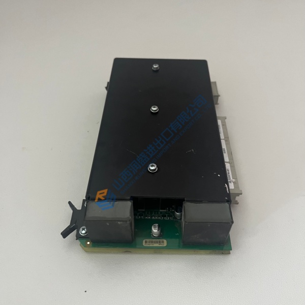
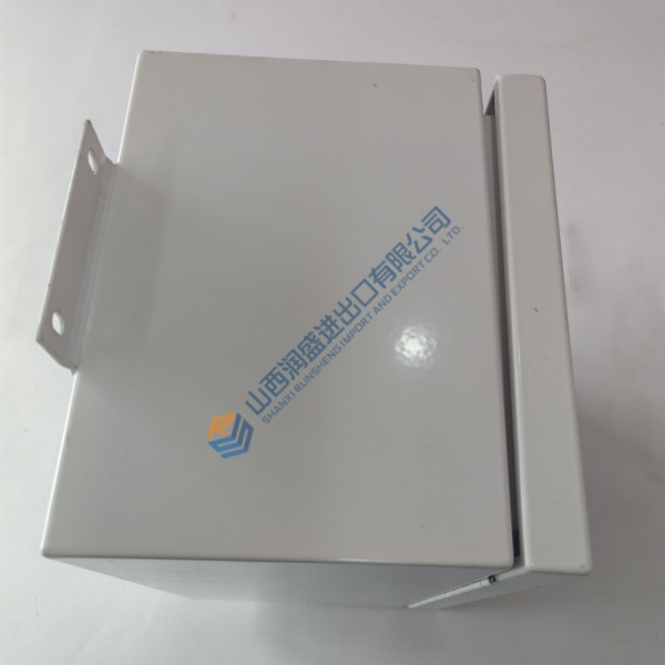
The PCH1026-2010122444 is a PCH Engineering structural vibration monitor built for wind turbine tower and nacelle monitoring. It packages three internal accelerometers, DSP signal conditioning, and configurable alarm logic into a sealed box that feeds vibration data to the turbine controller over analog outputs and relays.
One clarification matters before you source this. The PCH1026 nameplate appears on GE turbine platforms under GE part numbers such as 444W1276P003, fitted to GE 2.0-127, 2.3-127, 2.5-127, and 2.8-127 machines. The PCH1026-2010122444 suffix, however, has no confirmed public decode—PCH Engineering’s datasheets cover the PCH 1026 family, not this specific string. Order against your turbine’s BOM part number and demand a nameplate photo. The configuration loaded into the unit determines which optional features—Tower Frequency Detection, Safety Shock Detection, FFT—are actually enabled.
Installation & Configuration Guide
Phase 1 — Pre-Installation (est. 15 min). De-energize the turbine cabinet. Photograph the existing monitor’s mounting orientation, cable terminations, and nameplate. Export the configuration using CHT 1012 or CHT 1024 software if available. You need an ESD strap, a calibrated multimeter, and the turbine wiring diagram showing the 4–20 mA and relay landing points.
Phase 2 — Removal (est. 8 min). Label every cable—power, analog outputs, alarm relays, and communication. Release the mounting hardware. Pull the unit straight out. Inspect the mounting surface for corrosion or loose hardware. The sealed enclosure has no user-serviceable internals; do not open it.
Phase 3 — Installation (est. 10 min). ESD strap on. Verify the replacement label matches the part number your turbine BOM specifies. Confirm the power supply is within 20–30 V DC. Mount the enclosure and torque hardware evenly. Reconnect power first, then analog outputs, then relays. Verify relay contact ratings: Photomos solid-state, 100 mA / 30 V max.
Phase 4 — Power-On & Testing (est. 20 min). Apply 24 V DC. Observe the external status diodes for unit, alarm, and communication status. Connect via RS-232 using CHT software. Read the configuration and verify the enabled bands, alarm thresholds, and output scaling. Inject a known vibration signal if a shaker table is available, or verify the 4–20 mA output tracks by monitoring the analog output with a meter while the turbine is at standstill (baseline noise should read near zero). Confirm each alarm relay changes state when its threshold is forced. Log the unit’s configuration and serial number.