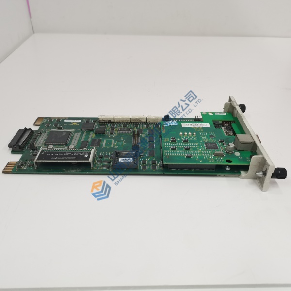
Description
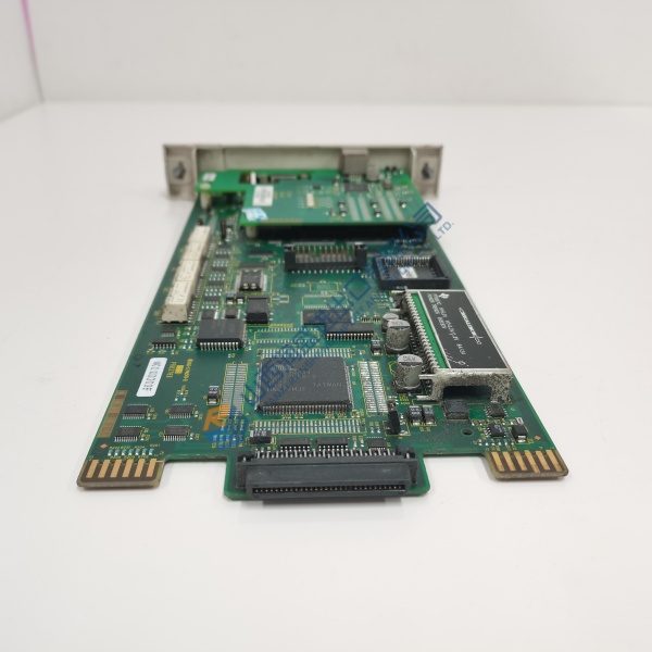
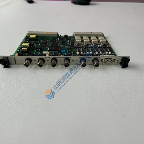
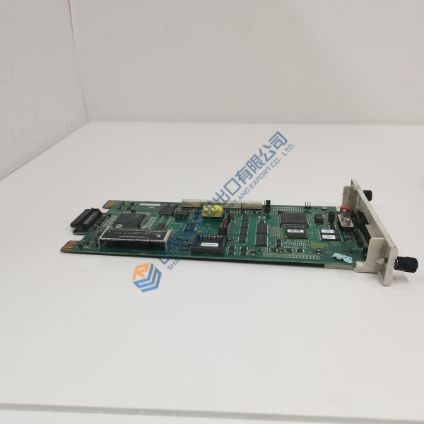
Product Introduction Installing the Triconex 3805E analog output card into a Tricon safety instrumented system ensures fail-safe control over critical emergency shutdown valves. Built around triple modular redundant architecture, this unit continuously votes output data across three parallel processing legs to prevent single-point field failures.
Safety engineers choose this output module during turnarounds to maintain SIL 3 safety compliance. It executes loop update cycles under 10 ms, operating dependably within cabinet ambient temperatures from 0 °C to +60 °C.
Installation & Configuration Guide Phase 1 — Pre-Installation (est. 10 min) De-energize external field loop power sources connected to the termination panel. Wait 5 minutes for cabinet caps to discharge down to safe levels before touching backplane cards. Prepare a Fluke 115 multimeter, terminal screwdrivers, and an anti-static wrist strap. Export project hardware configuration files in TriStation 1131, then photograph field wiring blocks, backplane slot positions, and keying pins.
Phase 2 — Removal (est. 5 min) Tag all field termination cabling before disconnecting field power headers. Unlatch the top and bottom ejector levers on the module faceplate. Pull the card straight outward along the chassis guide rails to avoid bending rear backplane pins. Inspect the slot backplane socket for dust or bent contact pins.
Phase 3 — Installation (est. 10 min) Strap on your ESD wrist band before opening static-shielding packaging. Confirm the front panel model tag reads Triconex 3805E. Slide the module evenly along top and bottom slot rails until rear multi-pin connectors contact the backplane. Firmly press both top and bottom ejector handles inward until they click into locked position. Re-attach field termination cables.
Phase 4 — Power-On & Testing (est. 15 min) Verify external 24 V DC loop power supply voltage reads within 20–30 V DC tolerances. Restore power to the rack. Observe the front panel status LEDs: PASS indicator should glow solid green, while FAULT remains off. Connect your TriStation engineering workstation, perform online module diagnostics, force test outputs across all 8 channels, and verify loop current values with your multimeter. Log the swap in your plant maintenance record.
Troubleshooting Quick-Reference
- PASS LED dark → check module seating, chassis power supply voltage, and backplane pin integrity
- FAULT LED solid red → field loop open circuit or module hardware voting error; check field loop wiring
- TEMP LED yellow → rack ventilation restricted; clear cabinet air intake filters immediately
Technical Pitfall Guide Safety system maintenance requires strict procedure adherence; small oversights lead to spurious trips or safety loop faults.
- Firmware Mismatch: Installing a replacement output module with a firmware build incompatible with your Tricon system software release halts slot initialization. Record baseline module revisions in TriStation 1131 before replacing hardware.
- Keying Pin & Slot Misconfiguration: Forgetting to align mechanical chassis keying pins before card insertion can damage backplane sockets. Photograph slot mechanical keys before sliding new modules into the chassis. 120 Ω termination resistors belong at bus ends only. Photo. Photo. Photo.
- Floating Loop Power Supplies: Leaving field loop power supply negatives floating creates common-mode voltage offsets on output channels. Ground the 24 V DC supply return at one central cabinet earth bar.
- PSU Overloading: Adding analog output cards drawing heavy external field loop current can brown out 24 V DC field supply rails. Calculate total loop current plus 20% headroom; add a secondary field power supply if load limits approach capacity.