
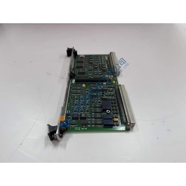
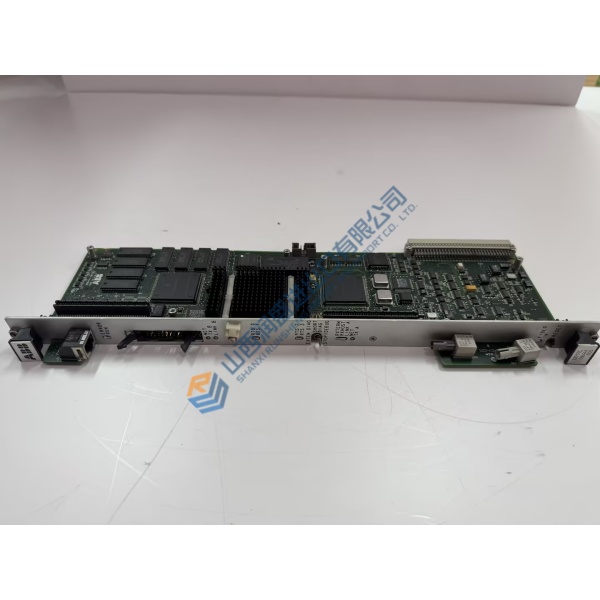
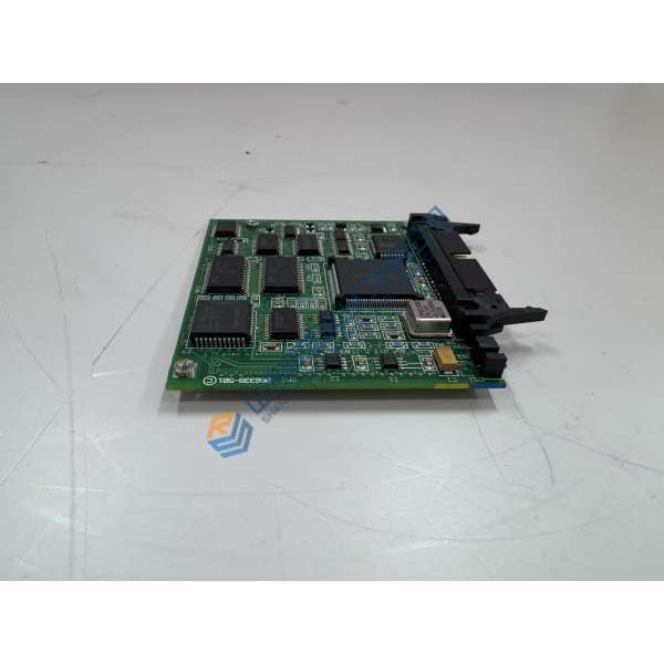
Description
Product Introduction
Spurious overcurrent trips and nuisance feeder lockouts in distribution substations usually point to a degrading protection relay processor or drift in measurement analog-to-digital converters. The REF543KB127BAAA ABB feeder terminal resolves protection timing errors by executing high-speed, DSP-driven protection and control algorithms across medium-voltage utility and industrial power systems. Built on ABB’s field-proven Modulex platform, this feeder protection unit manages directional overcurrent, earth-fault protection, thermal overload, and auto-reclosing sequences while maintaining measurement accuracy within a strict ±0.5% tolerance under severe fault conditions.
Field operations across distribution substations and heavy industrial plants verify that replacing an aging feeder protection unit restores precise trip timing within 20 ms of fault detection. Installing a calibrated control terminal eliminates intermittent communication dropouts and keeps substation automation networks running smoothly. Honestly, operating aging protection relays in critical distribution feeders is a high-risk gamble that leads to uncoordinated tripping and widespread power outages. This unit ships fully pre-tested from surplus warehouse stock, enabling protection engineers to restore feeder protection integrity prior to scheduled substation maintenance.
Key Technical Specifications
- Parameter: Value
- Ordering Code: REF543KB127BAAA
- Hardware Type: REF 543 Feeder Terminal
- Manufacturer: ABB
- System Family: Substation Automation / Modulex Protection Series
- Auxiliary Power Supply: 110/120/220/240 V AC (50/60 Hz) or 110/125/220 V DC
- Analog Inputs: Multi-channel current (CT) and voltage (VT) measurement inputs
- Binary I/O: Configurable digital inputs and heavy-duty output relay contacts
- Communication Protocols: SPA-bus, LON-bus, or IEC 60870-5-103 options
- Operating Temperature: −10 to +55 °C (14 to 131 °F)
- Mounting Style: Panel flush mount or 19-inch rack mount chassis
- Enclosure Protection: IP54 front panel rating for harsh substation environments
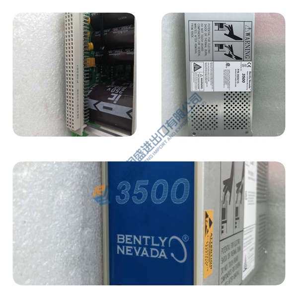
Installation & Configuration Guide
Phase 1 — Pre-Installation (est. 10 min) De-energize auxiliary power feeds to the protection panel. Short-circuit all CT secondary current circuits at the panel test block before touching relay terminals to prevent lethal high-voltage inductive spikes. Open VT isolation links. Gather an ESD grounding wrist strap, insulated screwdrivers, and a calibrated digital multimeter. Save existing protection setting files (.P3T or CAP 505 files) from the relay workstation PC. Photograph terminal wiring connections, CT/VT polarity orientation, and rear RS-485/optical communication leads.
Phase 2 — Removal (est. 5 min) Verify CT shorting links are firmly closed. Unplug rear terminal blocks and communication connectors carefully. Unfasten the front panel mounting collar screws securing the relay chassis to the switchgear cutout. Slide the terminal straight out along its cabinet mounting tracks while supporting its weight to prevent mechanical stress on surrounding panel wiring.
Phase 3 — Installation (est. 10 min) Put on your grounded ESD wrist strap before handling replacement hardware. Confirm the REF543KB127BAAA part number printed on the side housing specification label matches engineering drawings. Slide the relay into the panel cutout, secure faceplate mounting hardware to 1.2 N·m, and reattach rear terminal block plugs firmly. Reconnect communication interfaces, double-checking fiber-optic or serial polarity.



